
- Catalogs
- DANFOSS Refrigeration & Air Conditioning
- Electromechanical controls


Electromechanical controls

Electromechanical controls
KP temperature controls are designed for deep freeze, refrigeration, and air conditioning systems, offering a wide regulating range. They feature welded bellows for reliability, compact size for easy installation, and short bounce times for extended life. These controls can connect directly to single-phase AC motors or be used in control circuits for DC and large AC motors. Options include vapour or adsorption charge for frost protection and signal connection.
KP temperature controls are approved by several maritime and safety organizations, including GL, DNV, UL, RINA, BV, LR, and RMRS. Marine approvals do not cover KP98 dual temperature controls.
Operating within -40°C to +65°C, with a maximum of +80°C for short periods, these controls feature an SPDT switch with specific contact load capacities for AC and DC currents. The enclosure is rated IP 30 and CE-marked for European sales.
KP thermostats use a snap-action switch mechanism for high contact load and vibration resistance, supporting long mechanical and electrical life. The KP 98 dual thermostat protects against high discharge gas temperatures and ensures suitable oil temperatures in compressors.
Key terms such as differential, mechanical differential, and operating differential are explained, crucial for understanding the operation of the temperature controls.
Temperature controls with automatic reset allow setting the upper activating temperature and differential. The document details vapour and adsorption charges, explaining their roles in temperature regulation and protection against deformation.
The KP 61-81 models weigh approximately 0.4 kg, while the KP 98 model weighs about 0.6 kg. Details on mounting options and dimensions for various models are provided.
The document is a technical brochure for Danfoss RT series temperature controls, including differential thermostats. These controls are designed for industrial and marine applications, offering features such as waterproof versions (IP 66), a wide regulating range, and compatibility with both AC and DC. The RT series includes models for general applications, differential temperature controls, and special versions for PLC applications.
The RT series temperature controls have a single-pole changeover switch, with contact position dependent on bulb temperature and set scale value. Various models (RT 2, RT 3, RT 4, etc.) are listed with approvals from organizations like Lloyd’s Register of Shipping and Germanischer Lloyd. The controls conform to standards such as EN 60730-2-1 to 9 and carry the CE mark according to EN 60947-4, -5.
Detailed technical data includes cable connection specifications, enclosure ratings (IP 66 or IP 54), wire dimensions, and permissible ambient temperatures. A comprehensive table of regulation ranges, differential settings, and maximum bulb temperatures for various RT models is included.
The RT temperature controls consist of a sensor, capillary tube, and bellows element. The thermostatic element reacts to temperature variations, with the main spindle transferring movement to the switch. The document explains the design and function of both standard RT controls and RT L controls with neutral zones, allowing for floating control.
Key terms such as floating control, hunting, neutral zone, and mechanical differential are defined, crucial for understanding the operation and application of the RT series controls.
The brochure describes vapour charge and adsorption charge used in thermostatic elements. Vapour charge utilizes the pressure-temperature relationship of saturated vapour, while adsorption charge involves a superheated gas and a solid with a large adsorption surface.
Detailed ordering information includes code numbers for standard units and special switches, outlining types of switches available, such as SPDT and SPST, with specifications for contact ratings and reset options.
The Danfoss RT series temperature controls are versatile and robust solutions for temperature regulation in industrial and marine settings. The brochure provides comprehensive technical details and ordering information to assist in selecting the appropriate model for specific applications.
- Specifications: Designed for various plant systems to maintain a specific temperature differential between two media, including a single-pole changeover switch and two bellows elements for temperature control.
- Functionality: Operates by utilizing the temperature differential between LT and HT sensors, with the main spindle moving based on this differential to activate or deactivate switch contacts.
- Application Example: For an RT 14 thermostat with a range of -5 to +30°C, a scale correction factor adjusts the activation temperature based on ambient conditions.
- Features: Used in refrigeration and air conditioning systems to manage suction and discharge pressures, equipped with a snap-action function for reliability, and can connect to AC and DC motors.
- Technical Data: Detailed specifications include ambient temperature ranges, maximum working pressures, and contact load capacities. Available in various enclosures (IP30, IP44, IP55) and CE-marked.
- Materials: Made from tinbronze, nickel-plated steel, and stainless steel for durability and compatibility with different refrigerants.
- RT Differential Thermostat: Includes components such as LT and HT sensors, capillary tubes, bellows elements, and a setting disc for adjusting temperature differentials.
- KP Pressure Controls: Feature a compact design with a fully welded bellows element, offering high reliability and resistance to vibration and shock.
- Applications: Suitable for use in process plants, ventilation systems, and refrigeration and heating plants.
- Approvals: Approved by various international standards and organizations, including CE, UL, and several maritime registers.
Outlines ordering information and specifications for pressure controls used with HCFC and non-flammable HFC refrigerants, specifying BSP external threads according to ISO 228-1 and highlighting safety pressure controls approved by EN 12263 and CE marked according to the Pressure Equipment Directive (PED).
Lists various types of pressure controls, including RT 36B, RT 36S, RT 6W, RT 6B, RT 6S, RT 30AW, RT 30AB, RT 30AS, RT 6AW, RT 6AB, and RT 6AS, each with specific regulation ranges, differential settings, reset mechanisms, and maximum working and test pressures. Notes suitability for R717 refrigerants.
Features a bellows system connected to the pressure side of the controlled system, with the main spindle and spring balancing the pressure, transferring movement to a switch. Details components such as the setting knob, regulation range scale, main spring, and switch.
Equipped with a double bellows system to prevent loss of system charge in case of rupture, tested and approved by TÜV according to EN 12263. Emphasizes the fail-safe function, automatically stopping the plant if pressure exceeds set values.
Describes various switch types, including those with automatic and manual resets, gold-plated contacts, and non-snap action changeover contacts, specifying contact load capacities for alternating and direct currents.
Defines key terms such as floating control, hunting, neutral zone, and snap function. Explains setting mechanisms for RT pressure controls with both automatic and manual resets, detailing how to set the lowest and highest activating pressures.
Differential pressure controls are primarily used for protecting against low differential pressure across liquid circulation pumps and safeguarding lubricating oil pressure in refrigeration compressors.
Concludes with dimensions and weight specifications for the pressure control units.
Outlines features of differential pressure control devices, types MP 54 and MP 55, including fixed and adjustable differentials, narrow switch differential accuracy, and reliable stainless steel bellows. Designed for use with HCFC and non-flammable HFC refrigerants, serving as safety switches to protect refrigeration compressors from low lubricating oil pressure.
UL listed for use in the USA and Canada, ensuring compliance with safety standards.
Describes connection points for the lubrication system and refrigeration plant, the setting disc for adjusting differential pressures, and the reset button. MP 54 has a fixed differential, while MP 55 allows for adjustable settings.
Key terms include differential range, scale reading, operating range, contact differential, and release time, crucial for understanding the operation of the pressure control devices.
Explains the operation of the pressure control devices, which stop the compressor if oil pressure falls below the set level. Devices have separate safety and operational circuits, with a timer activating when oil pressure is insufficient.
Provides detailed technical specifications, including materials in contact with the medium, ambient temperature range, switch differential, maximum working pressure, control voltage, and electrical connection details.
Includes ordering codes for different configurations of the MP 54 and MP 55, specifying control differential, regulation range, time relay delay time, and connection types.
Provides physical specifications of the devices, with a net weight of approximately 1.8 lbs.
Catalog excerpts

Temperature controls, type KP Contents Page Features . . . . . . . . . . . . . . . . . . . . . . . . . . . . . . . . . . . . . . . . . . . . . . . . . . . . . . . . . . . . . . . . . . . . . . . . . . . . . . . . . . . . . . . . . 287 Approvals . . . . . . . . . . . . . . . . . . . . . . . . . . . . . . . . . . . . . . . . . . . . . . . . . . . . . . . . . . . . . . . . . . . . . . . . . . . . . . . . . . . . . . . .288 Ship approvals . . . . . . . . . . . . . . . . . . . . . . . . . . . . . . . . . . . . . . . . . . . . . . . . . . . . . . . . . . . . . . . . . . . . . . . . . . . . . . . . . . . 288 Regulating range . . . . . . . . . . . . . . . . . . . . . . . . . . . . . . . . . . . . . . . . . . . . . . . . . . . . . . . . . . . . . . . . . . . . . . . . . . . . . . . . 288 Technical data . . . . . . . . . . . . . . . . . . . . . . . . . . . . . . . . . . . . . . . . . . . . . . . . . . . . . . . . . . . . . . . . . . . . . . . . . . . . . . . . . . . 288 Contact systems . . . . . . . . . . . . . . . . . . . . . . . . . . . . . . . . . . . . . . . . . . . . . . . . . . . . . . . . . . . . . . . . . . . . . . . . . . . . . . . . . 289 Ordering . . . . . . . . . . . . . . . . . . . . . . . . . . . . . . . . . . . . . . . . . . . . . . . . . . . . . . . . . . . . . . . . . . . . . . . . . . . . . . . . . . . . . . . . 289 Design / Function . . . . . . . . . . . . . . . . . . . . . . . . . . . . . . . . . . . . . . . . . . . . . . . . . . . . . . . . . . . . . . . . . . . . . . . . . . . . . . . .291 Terminology . . . . . . . . . . . . . . . . . . . . . . . . . . . . . . . . . . . . . . . . . . . . . . . . . . . . . . . . . . . . . . . . . . . . . . . . . . . . . . . . . . . . . 292 Setting . . . . . . . . . . . . . . . . . . . . . . . . . . . . . . . . . . . . . . . . . . . . . . . . . . . . . . . . . . . . . . . . . . . . . . . . . . . . . . . . . . . . . . . . . . 293 Charges . . . . . . . . . . . . . . . . . . . . . . . . . . . . . . . . . . . . . . . . . . . . . . . . . . . . . . . . . . . . . . . . . . . . . . . . . . . . . . . . . . . . . . . . . 293 Dimensions and weights . . . . . . . . . . . . . . . . . . . . . . . . . . . . . . . . . . . . . . . . . . . . . . . . . . . . . . . . . . . . . . . . . . . . . . . . . 294
Open the catalog to page 1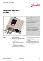
MAKING MODERN LIVING POSSIBLE Temperature controls, Type KP KP temperature controls are single-pole, double-throw (SPDT) temperature-operated electric switches. A KP temperature control can be connected directly to a single-phase AC motor of up to approx. 2 kW or installed in the control circuit of DC motors and large AC motors. KP temperature controls are used for regulation, but can also be seen in safety monitoring systems. KP temperature controls are available with vapour charge or with adsorption charge. With vapour charge the differential is very small. KP thermostats with adsorption charge...
Open the catalog to page 3
Technical brochure Temperature controls, type KP CE-marked in accordance with EN 60947-4/-5 for sale in Europe China Compulsory Certificate, CCC Ship approvals Germanischer Lloyd, GL Det Norske Veritas, DNV Underwriters Laboratories Inc., US – UL Registro Italiano Navale, RINA Bureau Veritas, France, BV Lloyd’s Register, LR Russian Maritime Register of Shipping, RMRS Note: Marine Approvals do not cover KP98 dual temperature controls Regulating range KP 61 Vapour range KP 62 KP 63 KP 68 KP 69 Technical data Ambient temperature -40 → +65°C (+80°C for max. 2 hours). Switch Single-pole, double-throw...
Open the catalog to page 4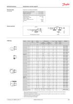
Technical brochure Temperature controls, type KP Technical data (continued) Properties according to EN 60947: Wire dimensions solid/stranded flexible, w/out ferrules flexible, with ferrules Tightning torque Rated impulse voltage Pollution degree Short circuit protection, fuse Insulation IP Contact systems Bulb type Setting range Capillarytube length Bulb must always be placed colder than the thermostat housing and capillary tube. The thermostat will then regulate independent of ambient temperature. B ulb can be placed warmer or colder than thermostat housing and capillary tube, but variations...
Open the catalog to page 5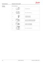
Technical brochure Temperature controls, type KP Ordering (continued) Thermostat bulb types C1: Ø 40 × 30 mm air coil C2: Ø 25 × 67 mm air coil (integral with thermostat) D1: Ø 10 × 85 mm double contact remote bulb D2: Ø 16 × 170 mm double contact remote bulb Note! Cannot be used in sensor (bulb) pocket E1: Ø 6.4 × 95 mm remote bulb E2: Ø 9.5 × 115 mm remote bulb E3: Ø 9.5 × 85 mm remote bulb Straight capillary tube Ø 25 × 125 mm remote duct coil
Open the catalog to page 6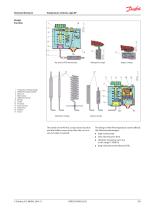
Technical brochure Temperature controls, type KP Design Function Vapour charge Key sketch of KP thermostats Adsorption charge 1. Temperature setting spindle 2. Differential setting spindle 3. Main arm 7. Main spring 8. Differential spring 9. Bellows 12. Switch 13. Terminals 14. Earth terminal 15. Cable entry 16. Tumbler 17. Sensor Vapour charge The switch in the KP has a snap-action function and the bellows move only when the cut-in or cut-out value is reached. The design of the KP temperature control affords the following advantages: high contact load ultra-short bounce time v...
Open the catalog to page 7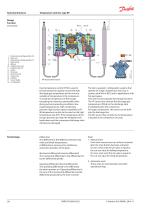
Technical brochure Temperature controls, type KP Design Function (continued) Temperature setting spindle, OIL Main arm Temperature setting spindle, HT Main spring Bellows Capillary tube, OIL Capillary tube, HT Switch Terminals Earth terminal Cable entry Tumbler Sensor (bulb) Locking plate Dual temperature control KP 98 is used to provide protection against excessively high discharge gas temperature and to ensure a suitable oil temperature in the compressor. To avoid the temperature of the hot gas exceeding the maximum permissible value during extreme operating conditions (low evaporating pressure,...
Open the catalog to page 8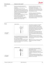
Technical brochure Temperature controls, type KP Temperature controls with automatic reset Set the upper activating temperature on the range scale. Set the differential on the "DIFF" scale. The temperature setting on the range scale will then correspond to the temperature at which the refrigeration compressor will be started on rising temperature. The compressor will be stopped when the temperature has fallen in relation to the differential setting. Note that the differential depends on the range setting. Therefore, the differential scale must only be used as guideline. If with low stop temperature...
Open the catalog to page 9All DANFOSS Refrigeration & Air Conditioning catalogs and technical brochures
 ICLX
ICLX25 Pages
 Shut-off ball valve Type GBC
15 Pages


Archived catalogs
 Danfoss Industrial Refrigeration
32 Pages
 VSH088-G
28 Pages
 Danfoss scroll VZH serie
6 Pages
 Danfoss scroll VSH serie -
56 Pages
 VZH028-VZH044
4 Pages
 CXH140
6 Pages
 Counterfeit
3 Pages
 Level controls
92 Pages
 ADAP-KOOL ® Catalogue
222 Pages
 compressors MT - MTZ - NTZ
8 Pages
 Quick Selection Catalogue
359 Pages
 MCX General Catalogue
48 Pages
 EVR
EVR2 Pages
 R32 brochure
5 Pages
 Apexx™ SLV series
8 Pages
 SGN+ and SGI+ sales brochure
2 Pages


- DANFOSS valve
- Manual valve
- Control valve
- Ball valve
- Temperature probe
- Electrically operated valve
- Regulating valve
- Flange valve
- Liquid filter
- On/off valve
- Flap valve
- Check valve
- Resistance temperature sensor
- Lever valve
- Electric valve
- Pressure transmitter
- Gas solenoid valve
- 2-way solenoid valve
- NC solenoid valve
- Level limit switch