- Catalogs
- Danfoss Power Solutions
- PLUS+1 I/O Modules
- Products
- Catalogs
- News & Trends
- Exhibitions
PLUS+1 I/O Modules
1 /38Pages
PLUS+1 I/O Modules
1 /38Pages
Catalog excerpts

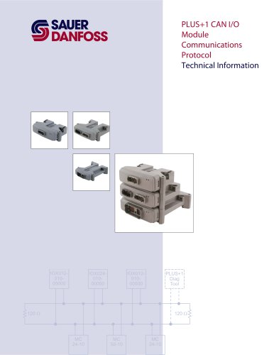
PLUS+1 CAN I/O Module Communications Protocol Technical Information
Open the catalog to page 1
PLUS+1 CAN I/O Module Communications Protocol Technical Information About this Manual To help you quickly find information in this manual, the material is divided into sections, topics, subtopics, and details, with descriptive headings set in red type. Section titles appear at the top of every page in large red type. In the PDF version of this document, clicking an item underlined in blue italic type jumps you to the referenced page in the document. Special Text Formatting Controls and indicators are set in bold black type. A Table of Contents (TOC) appears on the next page. In the PDF version...
Open the catalog to page 2
PLUS+1 CAN I/O Module Communications Protocol Technical Information ©2010 Sauer-Danfoss. All rights reserved. Sauer-Danfoss accepts no responsibility for possible errors in catalogs, brochures and other printed material. Sauer-Danfoss reserves the right to alter its products without prior notice. This also applies to products already ordered provided that such alterations can be made without affecting agreed specifications. All trademarks in this material are properties of their respective owners. PLUS+1, GUIDE, and Sauer-Danfoss are trademarks of the Sauer-Danfoss Group. The PLUS+1 GUIDE, PLUS+1...
Open the catalog to page 3
PLUS+1 CAN I/O Module Communications Protocol Technical Information (This page is intentionally blank.)
Open the catalog to page 4
PLUS+1 CAN I/O Module Communications Protocol Technical Information Contents T Adobe Reader links entries in this table of contents. To follow a link, click an entry.
Open the catalog to page 5
PLUS+1 CAN I/O Module Communications Protocol Technical Information Contents
Open the catalog to page 6
PLUS+1 CAN I/O Module Communications Protocol Technical Information Message Timing Information In the following section on message structures, the repetition time is specified. If the repetition time is set to zero, then the message is disabled and is not sent. If the repetition time is not zero, then the message is active and is transmitted periodically at the interval specified by the repetition time. (The following tables identify the repetition time as the Rate.) To change the repetition time, use the Configure Timing message (SUBCMD 12.) Some of the messages are referred to as optimized...
Open the catalog to page 7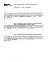
PLUS+1 CAN I/O Module Communications Protocol Technical Information Messages Based on the Sub-Identifier Supply (CMD 0) This frame is transmitted from the I/O device continuously with a default cycle time. CMD *Measured supply voltage in mV. †Measured sensor voltage in mV. ‡Measured shield voltage in mV. Dig_In (CMD 16) This frame is transmitted from the I/O device continuously with a default cycle time. This message has to be activated. By default, packed frames are used. CMD *Identifies the channel. †Actual pin status. Ana/Temp/Rheo (CMD 32) This frame is transmitted from the I/O device continuously...
Open the catalog to page 8
PLUS+1 CAN I/O Module Communications Protocol Technical Information Messages Based on the Sub-Identifier Dig and Ana/Temp/Rheo Opt I (CMD 33) This frame is transmitted from the I/O device continuously with a default cycle time. This message is a packed frame and is activated by default if the device does have these inputs. Values not available on the I/O device are set to zero. CMD *Actual measured value of the first channel; mV in an analogue configuration; otherwise an Ω value. †Actual measured value of the second channel; mV in an analogue configuration; otherwise an Ω value. ‡ Bit pattern...
Open the catalog to page 9
PLUS+1 CAN I/O Module Communications Protocol Technical Information Messages Based on the Sub-Identifier Dig/Ana Opt I (CMD 49) This frame is transmitted from the I/O device continuously with a default cycle time. This message is a packed frame and is activated by default if the device does have these inputs. Values not available on the I/O device will be set to zero. CMD *Actual measured value of the first channel in mV. †Actual measured value of the second channel in mV. ‡Actual measured value of the third channel in mV. §Bit pattern for the first 3 digital inputs; bit 0 is channel 0. Dig/Ana...
Open the catalog to page 10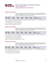
PLUS+1 CAN I/O Module Communications Protocol Technical Information Messages Based on the Sub-Identifier Dig/Ana/Freq Opt I (CMD 65) This frame is transmitted from the I/O device continuously with a default cycle time. This message is a packed frame and is activated by default if the device does have these inputs. Values not available on the I/O device will be set to zero. CMD *Actual measured value in mV on the first analogue input. †Actual measured value in mV on the second analogue input. ‡Actual measured value in mV on the third analogue input. §Bit pattern of the first 3 digital inputs;...
Open the catalog to page 11
PLUS+1 CAN I/O Module Communications Protocol Technical Information Messages Based on the Sub-Identifier Dig/Ana/Freq Opt IV (CMD 68) This frame is transmitted from the I/O device continuously with a default cycle time. This message is a packed frame and is activated by default if the device does have these inputs. Values not available on the I/O device will be set to zero. CMD *Actual measured frequency in Hz on the fourth input. †Actual measured frequency in Hz on the fifth input. ‡Actual measured frequency in Hz on the sixth input. Dig/Ana/Freq Opt V(CMD 69) This frame is transmitted from...
Open the catalog to page 12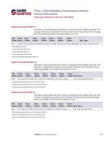
PLUS+1 CAN I/O Module Communications Protocol Technical Information Messages Based on the Sub-Identifier Dig/Ana/Freq Opt VII (CMD 71) This frame is transmitted from the I/O device continuously with a default cycle time. This message will only be transmitted if the device does have this type of input. This message has to be activated; by default the packed frames are used. CMD Rate Name *Indentifies the channel. †Actual measured value in mV. ‡Actual measured frequency. §Actual measured period (15-bit). #Status of the digital input (MSB of CAN B 7). Dig/Ana/Freq Opt VIII (CMD 72) This frame is...
Open the catalog to page 13
PLUS+1 CAN I/O Module Communications Protocol Technical Information Messages Based on the Sub-Identifier Dig/Ana/Freq Opt X(CMD 74) This frame is transmitted from the I/O device continuously with a default cycle time. This message is a packed frame and has to be activated if the device does have these inputs. Values not available on the I/O device will be set to zero. CMD Rate Name *Actual measured period, value in ms on the seventh input †Actual measured period, value in ms on the eighth input ‡Actual measured period, value in ms on the ninth input Digital Out Status (CMD 80) This frame is transmitted...
Open the catalog to page 14All Danfoss Power Solutions catalogs and technical brochures
 PVG 16
2 Pages
 PLUS1 Toolbox
16 Pages
 WS403
WS4032 Pages
 WS403-J
2 Pages
 WS503 / WS503-BP
2 Pages
 WS103
WS1032 Pages
 Product Range
4 Pages
 Orbital Motors General
36 Pages
 TMT new hydraulic motor
4 Pages
 Fan Drive Gear Motors
8 Pages
 Hydraulic Fluids and Lubricants
20 Pages
 PVG Product Brochure
8 Pages
 H1 Family Brochure
8 Pages


Archived catalogs
 Sauer Danfoss - All Products
30 Pages
 D Series Gear Pumps
36 Pages

- Danfoss pump
- Industrial pump
- Pump with electric motor
- Stationary pump
- Electromotor
- Seawater pump
- Self-priming pump
- Compact pump
- Automation software solution
- Piston pump
- Directional control valve
- Control software
- High-efficiency electromotor
- High-pressure pump
- DC-DC converter
- Compact electromotor
- Measurement software
- Valve actuator
- Friction brake
- High-efficiency pump