
- Catalogs
- Danfoss Power Solutions
- Orbital Motors General


- Products
- Catalogs
- News & Trends
- Exhibitions
Orbital Motors General

Orbital Motors General
Danfoss is a leading manufacturer of low-speed, high-torque orbital motors, offering over 3,000 variants. These motors are categorized by type, size, and shaft versions, with displacements ranging from 8 cm³ to 800 cm³ per revolution and speeds up to 2,500 rpm for smaller types and 600 rpm for larger types. Maximum operating torques range from 13 N•m to 2,700 N•m, with outputs from 2.0 kW to 70 kW.
- Smooth operation across speed ranges
- Constant torque over wide speed ranges
- High starting torque and return pressure
- High efficiency and long life under extreme conditions
- Robust design with high radial and axial bearing capacity
- Suitable for open and closed-loop hydraulic systems
- Corrosion-resistant parts
- Wheel motors with recessed mounting flange
- Motors with needle bearings, low leakage, or integrated brakes
- Motors with integrated flushing valves or speed sensors
- Construction and agricultural equipment
- Material handling and lifting equipment
- Forestry and lawn equipment
- Marine and special-purpose machinery
Orbital motors convert hydraulic energy into mechanical energy using a fixed displacement high-torque design. The speed is determined by oil flow rate, and torque by pressure differential. The internal gear design transmits output torque and speed.
- OML, OMM, OMP, DH: Compact design, suitable for moderate pressures.
- OMR, OMH, DS: Gear rim with rollers for high efficiency and long life.
- OMEW: Disc valve on output shaft, ideal for demanding conditions.
- OMS, OMT, OMV: Suitable for rough conditions with high efficiency.
- TMT: Meets high-pressure demands with good characteristics.
- Corrosion-resistant versions: OMP C and OMR C
- Wheel motor versions: OMPW, OMRW, OMSW, etc.
- Super low leakage motor: OMR NA
- Short and ultrashort motors: OMSS, OMTS, OMVS, etc.
- Motors with integrated brakes and flushing valves
- Motors with tacho connections and speed sensors
The document provides detailed technical information on various types of orbital motors, specifically focusing on the OM-EM and OMT N motor types. The OM-EM is integrated into the sensor housing, while the OMT N is noted for its high bearing capacity, making it suitable for road rollers and similar equipment.
Motor Selection and Function Diagrams
Motor selection is based on application requirements, torque, and speed. Function diagrams illustrate the relationship between operating torque and speed at different pressure drops and oil flows. These diagrams, also known as shell diagrams, help in understanding the motor's performance under various conditions.
Continuous and Intermittent Operation
The function diagrams are divided into continuous and intermittent operation areas. Continuous operation ensures optimal efficiency and lifespan, while intermittent operation is suitable for varying loads. Motors should not exceed intermittent speed or pressure drop for more than 10% of each minute, and peak loads should not exceed 1% of each minute.
Efficiency Considerations
Total efficiency is the product of volumetric and hydraulic-mechanical efficiencies. Volumetric efficiency relates to the oil converted to output shaft revolutions, while hydraulic-mechanical efficiency pertains to pressure converted to output shaft torque. Efficiency graphs in function diagrams assist in selecting the appropriate motor.
Motor Size and Application
Motor size is determined by continuous and intermittent values, ensuring pressure peaks do not exceed maximum values. The document provides examples of selecting motor sizes based on specific application requirements, such as speed and torque.
Shaft Load and Bearing Life
Hydraulic motors must handle radial and axial forces. Danfoss motors use needle or tapered roller bearings to absorb these forces. Bearing life is inversely proportional to speed, and lower shaft loads result in longer bearing life. Maximum shaft load limits are provided to prevent mechanical breakdown.
Shaft Seal Pressure
Danfoss motors offer different shaft seals, including standard, high-pressure, and Viton seals, each suitable for specific conditions and fluids. The document outlines the characteristics and temperature ranges for these sealing materials.
Conclusion
The document provides comprehensive guidelines for selecting and operating Danfoss orbital motors, emphasizing efficiency, load handling, and proper motor sizing to ensure optimal performance and longevity.
1. Pressure Management: The pressure on the shaft seal must not exceed the maximum permissible pressure as indicated in the subcatalogue. For motors without a check valve and drain line, the shaft seal pressure is the average of the inlet and return pressures.
2. OMEW Motors: These motors have a high-pressure shaft seal and are available in clockwise (CW) and counter-clockwise (CCW) versions. The shaft seal pressure varies with the direction of rotation.
3. Drain Line Application: A drain line is recommended when the shaft seal pressure exceeds the maximum limit, especially in short motors combined with gears or in hydrostatic transmissions without a flushing valve.
Braking and Replenishment:
1. Braking Torque: Hydraulic motors can be used to brake loads by converting kinetic energy into hydraulic energy. The braking torque should be 1.2 to 1.3 times the effective motor torque, depending on the motor type.
2. Dual Shock Valve: The opening pressure of the dual shock valve regulates braking torque and should be set at maximum oil flow.
3. Replenishment: Effective replenishment is crucial to avoid cavitation and ensure sufficient braking capacity. The charge pressure must be greater than the pressure drop in the motor oil channels.
Installation and Maintenance:
1. Installation: Ensure all hydraulic components are installed according to instructions, with correct joint contact and minimal material stress.
2. Starting Up: Fill the system with oil through a fine-mesh filter, run the drive motor at low speed, and ensure all components are correctly connected.
3. Maintenance: Regularly check oil condition, system leakage, and oil level. Use mineral oils with anti-wear additives and maintain oil contamination levels at 20/16 (ISO 4406) or better.
Oil and Temperature Management:
1. Oil Types: Use mineral hydraulic oil with anti-wear additives. Non-flammable or biodegradable fluids can be used, but their compatibility with operating conditions must be ensured.
2. Temperature and Viscosity: Maintain ambient temperatures between -30°C and +90°C, and oil temperatures between +30°C and +60°C. The recommended oil viscosity is between 20 mm²/s and 75 mm²/s.
3. Filtering: Maintain oil contamination levels at 20/16 (ISO 4406) using appropriate filters.
Company Overview:
Danfoss Power Solutions is a global leader in hydraulic and electronic components, providing advanced solutions for off-highway vehicles. They offer extensive support and service through a global network of partners.
Danfoss Power Solutions operates globally with locations in Germany, Denmark, the USA, and China. The company specializes in hydraulic and electronic components and systems.
Addresses and phone numbers for Danfoss locations in Germany, Denmark, USA, and China are provided for customer inquiries and support.
Danfoss disclaims responsibility for errors in printed materials and reserves the right to alter products without notice, even for products already ordered, as long as specifications remain unchanged.
- Bent Axis Motors
- Closed Circuit Axial Piston Pumps and Motors
- Displays
- Electrohydraulic Power Steering
- Electrohydraulics
- Hydraulic Power Steering
- Integrated Systems
- Joysticks and Control Handles
- Microcontrollers and Software
- Open Circuit Axial Piston Pumps
- Orbital Motors
- PLUS+1® GUIDE
- Proportional Valves
- Sensors
- Steering
- Transit Mixer Drives
- Comatrol
- Schwarzmüller-Inverter
- Turolla
- Valmova
- Hydro-Gear
- Daikin-Sauer-Danfoss
Catalog excerpts

MAKING MODERN LIVING POSSIBLE Technical Information Orbital Motors General
Open the catalog to page 1
Technical Information General, Orbital Motors Revision history Table of revisions Date Converted to Danfoss layout - DITA CMS
Open the catalog to page 2
Technical Information General, Orbital Motors Selection of Motor Type Selection of Motor Size Bearing Dimensioning
Open the catalog to page 3
Technical Information General, Orbital Motors
Open the catalog to page 4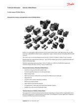
Technical Information General, Orbital Motors A wide range of Orbital Motors Characteristic, features and application areas of Orbital Motors Danfoss is a world leader within production of low speed orbital motors with high torque. We can offer more than 3,000 different orbital motors, categorised in types, variants and sizes (including different shaft versions). The motors vary in size (rated displacement) from 8 cm³ [0.50 in³] to 800 cm³ [48.9 in³] per revolution. Speeds range up to approximate 2,500 min-1 (rpm) for the smallest type and up to approximate 600 min-1 (rpm) for the largest type....
Open the catalog to page 5
Technical Information General, Orbital Motors A wide range of Orbital Motors Motors with corrosion resistant parts Wheel motors with recessed mounting flange OMP, OMR- motors with needle bearing OMR motor in low leakage version OMR motors in a super low leakage version Short motors without bearings Ultra short motors Motors with integrated positive holding brake Motors with integrated negative holding brake Motors with integrated flushing valve Motors with speed sensor Motors with tacho connection All motors are available with black finish paint The Danfoss Orbital Motors are used in the following...
Open the catalog to page 6
Technical Information General, Orbital Motors Conversion Factors 1 Nm = [8.851 lbf.in] 1 cm3 = [0.061 in3] 1 N = [0.2248 lbf ] 1 l = [0.22 UK gal] 1 bar = [14.50 psi] 1 l = [0.264 US gal] 1 mm = [0.0394 in] °F = [1.8 °C + 32]
Open the catalog to page 7
Technical Information General, Orbital Motors Orbital Motors, General Operating Principle Orbital motors convert hydraulic energy (pressure, oil flow) into mechanical energy (torque and speed). Danfoss orbital motors are of fixed displacement high-torque design. For a given oil flow and given pressure the displacement (size of motor) determines the speed and torque. For a given displacement (size of motor) the speed is determined by the oil flow rate and the torque is determined by the pressure differential. Gearwheel set The operating principle of the motors is based on an internal gear design,...
Open the catalog to page 8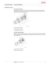
Technical Information General, Orbital Motors Orbital Motors, General Disc valve with valve drive OMS, OMT, OMV and TMT motors have a disc valve: The distributor valve has been separated from the output shaft and it is driven by a short cardan shaft [valve drive]. A balance plate counterbal-ances the hydraulic forces around the distributor valve. A: Output shaft D: Valve drive B: Cardan shaft E: Check valve C: Gearwheel set F: Disc valve Disc valve on the output shaft OMEW motors have a disc valvemounted on the output shaft. The cardan shaft rotates the disc valve and transfers mechanical energy...
Open the catalog to page 9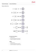
Technical Information General, Orbital Motors Selection of Motor Type Rollerless gear rim Spool valve integrated with output shaft Output shaft supported in slide bearings Rollerless gear rim Spool valve integrated with output shaft Output shaft supported in needle bearings
Open the catalog to page 10
Technical Information General, Orbital Motors Selection of Motor Type OMR, OMH, DS Gear rim with rollers Spool valve integrated with output shaft Output shaft supported in slide bearings Gear rim with rollers Spool valve integrated with output shaft Output shaft supported in needle bearings Gear rim with rollers Disc valve on output shaft Output shaft supported in needle bearings Gear rim with rollers Disc valve with separate valve drive Output shaft supported in tapered roller bearings Gear rim with rollers Disc valve with separate valve drive Output shaft supported in tapered roller bearings...
Open the catalog to page 11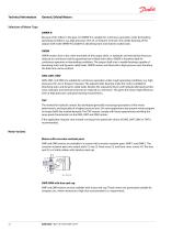
Technical Information General, Orbital Motors Selection of Motor Type OMRW N Because of the rollers in the gear rim OMRW N is suitable for continuous operation under demanding operating conditions: e.g. high pressures, thin oil, or frequent reversals. The needle bearings of the output shaft make OMRW N suitable for absorbing static and dynamic radial loads. OMEW OMEW motors have a disc valve mounted on the output shaft, i.e. hydraulic and mechanical losses are reduced to a minimum and the gearwheel set is fitted with rollers. OMEW is therefore ideal for continuous operation in demanding conditions....
Open the catalog to page 12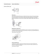
Technical Information General, Orbital Motors Selection of Motor Type Wheel motor OMP, OMR, OMS, OMT and OMV motors are available in wheel motor versions. The recessed mounting flange makes it possible to fit a wheel hub or a winch drum so that the radial load acts midway between the two motor bearings. This gives the best utilisation of the bearing capacity and is a very compact solution. Type designations of wheel motors are OMPW, OMPW N, OMRW N, OMEW, OMSW, OMTW, and OMVW. OMP/OMR with needle bearing For applications that want to use the OMP/OMR but must also consider other operating conditions...
Open the catalog to page 13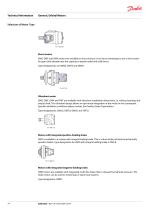
Technical Information General, Orbital Motors Selection of Motor Type Short motors OMS, OMT and OMV motors are available in short versions. It can be an advantage to use a short motor for gears that already have the capacity to absorb radial and axial forces. Type designations are OMSS, OMTS and OMVS. Ultrashort motor OMS, OMT, OMV and TMT are available with ultrashort installation dimensions, i.e. without bearings and output shaft. The ultrashort design allows an opti-mised integration of the motor in the counterpart. Special installation conditions please contact the Danfoss Sales Organisation....
Open the catalog to page 14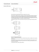
Technical Information General, Orbital Motors Selection of Motor Type OMT and TMT with integrated multi-disc brake is available in four versions: OMT FH, OMT FL, OMT FX and TMT FL. The brake is a spring activated multi-disc type that is released by a hydraulic pressure. OMT FH can work with high drop pressure [e.g. piloted from a shuttle valve in open loop systems], whereas OMT FL, OMT FX and TMT FL release the brake at low pressure [e.g. piloted from the charge pump in closed loop systems]. OMT FX are particularly well-suited for applications that require very short installation dimensions,...
Open the catalog to page 15All Danfoss Power Solutions catalogs and technical brochures
 PVG 16
2 Pages
 PLUS1 Toolbox
16 Pages
 WS403
WS4032 Pages
 WS403-J
2 Pages
 WS503 / WS503-BP
2 Pages
 WS103
WS1032 Pages
 Product Range
4 Pages
 TMT new hydraulic motor
4 Pages
 Fan Drive Gear Motors
8 Pages
 Hydraulic Fluids and Lubricants
20 Pages
 PLUS+1 I/O Modules
38 Pages
 PVG Product Brochure
8 Pages
 H1 Family Brochure
8 Pages






Archived catalogs
 Sauer Danfoss - All Products
30 Pages
 D Series Gear Pumps
36 Pages

- Industrial pump
- Pump with electric motor
- Stationary pump
- Electromotor
- Seawater pump
- Self-priming pump
- Compact pump
- Automation software solution
- Directional control valve
- Control software
- Compact electromotor
- High-pressure pump
- High-efficiency electromotor
- Valve actuator
- Measurement software
- DC-DC converter
- High-efficiency pump
- Friction brake