
- Catalogs
- Daikin Applied
- CAT 624-2 AGZ-E Air Cooled Chiller

CAT 624-2 AGZ-E Air Cooled Chiller

CAT 624-2 AGZ-E Air Cooled Chiller
The AGZ-E series of air-cooled scroll-compressor chillers by Daikin Applied are designed for high efficiency, quiet operation, and compactness. They range from 30 to 70 tons, use R-410A refrigerant, and comply with ASHRAE Standard 90.1. These chillers are ideal for mission-critical applications due to RapidRestore® and Fast Loading Technology, which enable quick cooling restoration after power interruptions.
- Unit Design: Factory-assembled with a heavy-gauge steel base, offering a small footprint suitable for retrofit applications.
- Compressors: Hermetic scroll compressors provide excellent part-load efficiency and reduced operating costs.
- Evaporator: Compact, high-efficiency, dual-circuit brazed plate-to-plate heat exchanger.
- Condenser Coils: Made from aluminum alloy with optional materials and coatings for different environments.
- Control System: MicroTech III controller with advanced diagnostics, compatible with building automation systems using BACnet®, Modbus, and LonWorks®.
- Optional Features: Remote evaporators, pump packages, and a remote user interface panel for convenient access.
The chillers are flexible, available as packaged units or with remote evaporators, suitable for applications like data centers and healthcare facilities.
AGZ units are designed for low operating sound levels, with full load sound pressure levels as low as 60dB, making them "neighborhood friendly."
Detailed procedures and data are provided for selecting the appropriate chiller model based on specific requirements, including part-load performance for both 60 Hz and 50 Hz operations.
Includes dimensions, lifting and mounting weights, and electrical specifications necessary for installation and operation.
Various options are available, including different coil materials, coatings, and pump packages to meet specific environmental and operational needs.
Provides detailed specifications for engineers to ensure proper installation and operation of the chillers.
Maximum standby ambient temperature is 130°F (55°C), maximum operating ambient temperature is 105°F (40°C), extendable to 125°F (52°C) with an optional high ambient package. Minimum operating temperature is 32°F (0°C), which can be lowered to -10°F (-23°C) with a low ambient control option. The leaving chilled water temperature ranges from 40°F to 65°F (2°C to 18°C), and the operating chilled water delta-T range is 6°F to 16°F (3.3°C to 8.9°C).
Unit Placement: Designed for outdoor applications, installable on roofs or at ground level. Roof installations require a steel frame, while ground installations need a concrete slab with footings below the frost line. The foundation must be level and strong enough to support the unit's weight.
Service and Air Clearance: A minimum clearance of 4 feet (1.22 m) is required on all sides for service access. The advanced coil design allows for close unit spacing, but sufficient clearance must be maintained to ensure proper airflow and prevent capacity reduction and increased power consumption.
Spacing Requirements: Guidelines for unit spacing, including walls on one side, two units side-by-side, and three or more units side-by-side, are provided to ensure adequate airflow and service access.
Piping design must be conducted by a qualified professional. The chilled water circulating pump should discharge into the evaporator inlet, and a perforated basket strainer must be installed before the evaporator inlet. A water flow switch is necessary to prevent freeze-up under low or no flow conditions. Vibration eliminators and pressure gauges are recommended, and piping should be insulated to prevent heat loss and condensation. Additional protection measures are suggested for systems operating in freezing conditions.
Flow rates and pressure drops are specified for full load design purposes. Flow rates below the minimum can cause freeze-up and poor control, while rates above the maximum can lead to excessive pressure drops and erosion. Variable flow in the evaporator can reduce power consumption, but flow changes should not exceed 10% per minute.
Freeze protection is crucial for air-cooled water chillers in freezing temperatures. Insulation and electric heaters are provided, but additional measures such as draining the system or adding glycol are recommended for further protection. The evaporator heater cable should be powered separately for maximum protection.
Chilled water pumps should be controlled by the chiller's microprocessor to ensure proper operation and prevent issues such as freeze-up or lockout alarms. The document emphasizes the importance of allowing the chiller to control the pumps to avoid catastrophic failures.
Wind velocities greater than five mph can reduce discharge pressure and increase the minimum operating ambient temperature. Hail/wind guards are recommended for effective operation at designed ambient temperatures.
AGZ-E units operating in high ambient temperatures (105ºF to 125ºF) require an optional high ambient package, which includes a fan and filter to cool the control panel. Units with VFD low ambient fan control automatically include this option.
For freeze protection, adding glycol or draining the system is recommended. Failure to do so in freezing temperatures may lead to catastrophic evaporator failure.
The standard coils are made of aluminum alloy microchannel design, tested for durability in non-corrosive environments. Alternative coil options include aluminum fin/copper tube, BlackFinTM, copper fin/copper tube, and ElectroFinTM coatings, each offering varying levels of corrosion resistance and durability.
Sound levels are crucial for unit cost and efficiency. The document outlines sound pressure and power levels, measured according to AHRI Standard 370. Sound pressure varies with distance and surroundings, while sound power is a calculated quantity independent of environment.
AGZ-E chillers are suitable for various applications. Performance tables provide data for different temperatures and conditions. Adjustments for non-standard conditions are available, and specific examples illustrate selection processes for different scenarios.
- Chilled water temperature range: 54°F - 44°F
- Evaporator fouling factor: 0.0001
- Protection from freezing down to 0°F using 40% ethylene glycol concentration
1. Select 40% ethylene glycol concentration from Table 16 to protect against freezing at 0°F.
2. Apply adjustment factors for 40% ethylene glycol: Capacity = 0.980, kW = 0.992, GPM = 1.132, Pressure Drop = 1.557.
3. Select AGZ 050E from Table 19 and correct with 40% ethylene glycol factors.
4. Corrected capacity: 0.980 x 48.3 tons = 47.3 tons.
5. Corrected kW: 0.992 x 54.6 kW = 54.2 kW.
6. Calculate chilled water flow: 47.3 tons x 24 / 10°F = 113.5 gpm. Glycol flow at 40% solution: 1.132 x 113.5 gpm = 128.5 gpm.
7. Determine evaporator pressure drop using Figure 28: Enter at 128.5 gpm and read horizontally to obtain a pressure drop of 17 feet. Correct for 40% solution: 1.557 x 17 feet = 26.5 feet.
- Use SI tables and procedures similar to I-P units.
- Performance tables are based at sea level; refer to Table 16 for performance at different elevations.
- AHRI Certification applies to all 60Hz standard packaged models, excluding optional remote evaporators.
- Ethylene and propylene glycol correction factors are provided in Tables 14 and 15.
- Altitude correction factors and evaporator temperature drop factors are detailed in Table 16.
- Full load and part load performance data for 60 Hz and 50 Hz are available in Tables 17-20.
- Pressure drop data is illustrated in Figure 16 and Table 21.
The document provides detailed specifications for Rubber-In-Shear (RIS) Mounts Spring Isolator Mountings, specifically models 035, 040, 045, 050, and 030 AGZ-E. It includes electrical data for these models, focusing on wire sizing, power connections, and fuse recommendations.
1. Compressor RLA values are for wire sizing only, with normal operating current potentially lower.
2. Unit wire size ampacity (MCA) is calculated as 125% of the largest compressor-motor RLA plus 100% of other loads.
3. Control transformers are included, eliminating the need for separate 115V power.
4. Recommended power lead wire sizes are based on NEC standards, with copper or aluminum wire required for terminal block connections.
5. Fuse sizes are recommended at 175% of the largest compressor RLA plus 100% of other loads.
6. Maximum fuse or breaker size is 225% of the largest compressor RLA plus 100% of other loads.
7. Ambient temperature considerations for wire sizing are noted, with NEC Handbook references.
8. Electrical grounding must comply with national and local codes.
1. Single-point power supply requires a single disconnect, either fused or circuit breaker.
2. Power wiring can use copper or aluminum, sized per NEC/local codes.
3. Field wire size values apply to 75°C rated wire per NEC.
1. Voltage must be within 10% of the nameplate rating.
2. Voltage unbalance should not exceed 2%, with current unbalance 6-10 times the voltage unbalance.
The electrical control center houses operating and protection controls, motor starting components, and the MicroTech III controller. It includes power terminal blocks, control transformers, optional disconnect switches, and various protection systems.
Options for power connections include power blocks, disconnect switches, and compressor circuit breakers. The control panel is designed for high short circuit current ratings.
Diagrams for single-point and multi-point connections are provided, detailing connections for compressors, fan motors, and control circuits.
Features like RapidRestore® and Fast Loading allow for quick restart and full load achievement after power interruptions.
The document outlines the specifications for air-cooled scroll compressor chillers, including power loss duration, restart times, and full load capacity. It details the fast loading stand-by chiller, hot gas bypass, low ambient control, and high ambient control panel. The chiller can operate in various ambient temperatures and includes options for water flow switches, alarm bells, remote operator interface panels, and BAS interfaces.
Installation procedures include field installation of water flow switches, alarm bells, and remote operator interface panels. The document specifies the need for compliance with manufacturer's instructions for rigging and handling equipment.
The chillers must comply with AHRI 550/590-2003, ANSI/ASHRAE 15, ETL, cETL, NEC, and OSHA standards. They should meet ASHRAE Standard 90.1, 2010 efficiency standards and be ISO registered.
Recommendations include the use of vibration isolators, protective base guards, and coated fins for enhanced durability and performance. The document suggests using sound reduction measures and provides options for different condenser coil materials and coatings.
Options include single-point electrical connections, phase loss/voltage protection, convenience outlets, ground fault protection, dual pump control, and high short circuit current rating with single-point disconnect breaker switch.
The chillers are designed for stable operation at a minimum of 25% full load without hot gas bypass and support variable flow ranges. They can control leaving chilled fluid temperatures from 15°F to 65°F and must meet specified sound pressure levels.
Components include sealed hermetic scroll compressors, brazed plate evaporators, and condenser fans with various coil options. The refrigerant circuit includes filter-driers, sight glasses, and solenoid valves.
Maintenance is the owner's responsibility, following the manufacturer's instructions. The warranty covers a period of one year from equipment start-up, excluding refrigerant.
Catalog excerpts

Model AGZ-E Catalog 624-2 Air-Cooled Scroll-Compressor Chillers
Open the catalog to page 1
Contents Introduction . . . . . . . . . . . . . . . . . . . . . . . . . . . . . . . 3 Features and Benefits . . . . . . . . . . . . . . . . . . . . . . . 4 Application Considerations . . . . . . . . . . . . . . . . . . . 8 Sound Data . . . . . . . . . . . . . . . . . . . . . . . . . . . . . . . 14 Selection Procedure . . . . . . . . . . . . . . . . . . . . . . . 18 Performance Data . . . . . . . . . . . . . . . . . . . . . . . . . . 19 Part Load Performance Data (60 Hz) . . . . . . . . . . 22 Part Load Performance Data (50 Hz) . . . . . . . . . . 23 Pressure Drop Data . . . . . . . . . . . ....
Open the catalog to page 2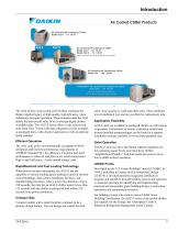
Introduction Introduction Air Cooled Chiller Products A Air-Cooled Scroll Compressor Chiller M Model AGZ-B • 10 - 34 RT Air-Cooled Scroll Compressor Chiller Model AGZ-E • 30 - 70 RT Model AGZ-D • 75 - 190 RT Remote Evaporator and Pump Package options available A Air-Cooled Screw Compressor Chiller Model AGS • 140 - 200 RT M Pathfinder™ Air-Cooled Screw Compressor Chiller Model AWS • 170 - 550 RT Standard, High, and Premium Efficency VFD and Remote Evaporator options available The AGZ family of air-cooled scroll chillers continues the Daikin Applied legacy of high quality, high efficiency, latest...
Open the catalog to page 3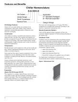
Chiller Nomenclature A G Z XXX E H Air-Cooled Global Design Scroll Compressor Nominal Tons Unit Design Features Features and Benefits Daikin AGZ air-cooled chillers are a product of our commitment to offer quiet, reliable, energy efficient equipment, incorporating high quality compressors, and innovative packaging. Construction AGZ chillers are factory-assembled and mounted on a heavygauge steel base. The base rails, supports and cabinetry are powder-coat painted for long life. The base distributes the unit weight for roof loading. Their small footprint allows smaller mounting pads or support...
Open the catalog to page 4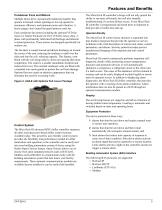
Features and Benefits Condenser Fans and Motors Multiple direct-drive, dynamically balanced propeller fans operate in formed venturi openings at low tip speeds for maximum efficiency and minimum noise and vibration. A heavy-gauge vinyl-coated fan guard protects each fan. The MicroTech III controller's design will not only permit the chiller to run more efficiently, but will also simplify troubleshooting if a system failure occurs. Every MicroTech III controller is programmed and tested prior to shipment to help provide a trouble-free start-up. Each condenser fan motor (including the optional...
Open the catalog to page 5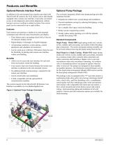
Features and Benefits Optional Remote Interface Panel Optional Pump Package In addition to the unit-mounted user interface provided with MicroTech® III controls, the AGZ chillers can be individually equipped with a remote user interface. It provides convenient access to unit diagnostics and control adjustments without having to access a rooftop or outdoor location. One remote panel can be connected to up to eight chillers. The on-board, integrated chilled water pump package provides important benefits: Features Each remote user interface is similar to its unit-mounted counterpart and offers the...
Open the catalog to page 6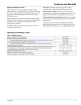
Features and Benefits Optional Variable Flow VFD The operating cost savings resulting from using variable chilled water flow via a pump VFD is well known. In the past, however, its usage has been somewhat limited by the cost and uncertainty of field installing the required system pressure differential sensors. Daikin Applied can now offer an innovative variable chilled water flow system completely self-contained within the pump package by simply ordering the optional pump VFD-no external sensors required. In addition to the sensorless operation, there are three other selectable operating modes:...
Open the catalog to page 7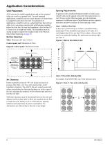
Application Considerations Unit Placement Spacing Requirements AGZ units are for outdoor applications and can be mounted either on a roof or at ground level. For roof mounted applications, install the unit on a steel channel or I-beam frame to support the unit above the roof. For ground level applications, install the unit on a substantial base that will not settle. Use a one-piece concrete slab with footings extended below the frost line. Be sure the foundation is level within 0.5” (13mm) over its length and width. The foundation must be strong enough to support the weights listed in the Physical...
Open the catalog to page 8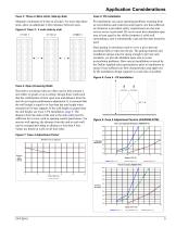
Application Considerations Case 3: Three or More Units, Side-by-Side Maintain a minimum of 6-feet on all sides. For more than three units, allow an additional 2-feet clearance between units. Pit installations can cause operating problems resulting from air recirculation and restriction and require care that sufficient air clearance is provided, safety requirements are met and service access is provided. Pit covers must have abundant open area at least equal to the chiller footprint.A solid wall surrounding a unit is substantially a pit and this data should be used. Figure 6: Case 3 - 3 units...
Open the catalog to page 9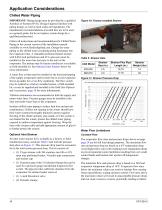
Application Considerations Chilled Water Piping IMPORTANT: Piping design must be provided by a qualified Architect or Systems HVAC Design Engineer familiar with piping design, as well as local codes and regulations. The manufacturer recommendations provided here are to be used as a general guide, but do not replace system design by a qualified professional. Follow all instructions and recommendations for Chilled Water Piping in the current version of the installation manual available on www.DaikinApplied.com. Design the water piping so the chilled water circulating pump discharges into the evaporator...
Open the catalog to page 10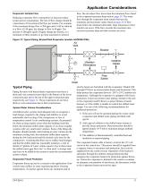
Application Considerations Evaporator Variable Flow Reducing evaporator flow in proportion to load can reduce system power consumption. The rate of flow change should be a maximum of 10 percent of the flow per minute. For example, if the maximum design flow is 200 gpm and it will be reduced to a flow of 140 gpm, the change in flow is 60 gpm. Ten percent of 200 gpm equals 20 gpm change per minute, or a minimum of three minutes to go from maximum to desired flow. Do not reduce flow lower than the minimum flows listed in the evaporator pressure drop section, page 24. The water flow through the evaporator...
Open the catalog to page 11All Daikin Applied catalogs and technical brochures
 Maverick® II systems
2 Pages
 Destiny® Indoor Air Handler
28 Pages
 PreciseLine®
4 Pages
 OptiLine™
2 Pages
 CAT 413-4 Steam Coils
23 Pages
 CAT 412-6 Water Heating Coils
32 Pages
 CAT 903 Air Terminal Units
106 Pages
 Daikin Applied 2014
247 Pages
 CAT 610-1 (AGSD 140-200 tons)
88 Pages


- Filter air purifier
- Air heater unit
- Mobile air purifier
- Daikin refrigeration unit
- Daikin stationary refrigeration unit
- HEPA filter air purifier
- Industrial air conditioner
- Air handling unit
- Ventilation unit
- Electric air heater unit
- Compact air conditioner
- Industrial air heater unit
- Outdoor air conditioner
- Inverter heat pump
- Wall-mounted air heater unit
- Commercial air conditioner
- Floor-standing air purifier
- Air purifier for commercial buildings
- Rooftop air conditioner
- Condensing unit