- Catalogs
- Daikin Applied
- CAT 607 - Direct Drive Fluid Coolers
CAT 607 - Direct Drive Fluid Coolers
1 /28Pages

CAT 607 - Direct Drive Fluid Coolers
1 /28Pages
Catalog excerpts

Direct Drive Fluid Coolers Catalog 607
Open the catalog to page 1
Document: Issue Date: Replaces: Manufactured in an ISO Certified Facility ©2013 Daikin Applied. Illustrations and data cover the Daikin Applied product at the time of publication and we reserve the right to make changes in design and construction at anytime without notice. Fluid Coolers
Open the catalog to page 2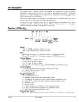
Introduction Our engineers have carefully selected and matched the components to provide superior performance, long service life, and a wide range of performance selections. Specifically engineered for outdoor installations, the fluid cooler is constructed of heavy gauge galvanized steel to resist corrosion in all climates. Fluid coolers are available in a wide range of sizes. Each model is available with several circuit options to provide the exact fluid cooler for your requirements. Our fluid coolers are designed to reduce the cost and time required for installation. Each unit is completely...
Open the catalog to page 3
Design Features Ease of Installation The fluid coolers are designed to reduce the cost and time required for installation. All lifting brackets are factory-installed, and the legs are designed for quick installation. Fan motors are factory wired to a control panel, providing a single point for field wiring. The control panel has a through-the-door disconnect switch. A wide variety of fan control panels can be factory mounted and wired, eliminating the need for a field-mounted, built-up control panel. Dynamic Stress Testing Fan motor and blade assemblies undergo dynamic stress testing. This testing...
Open the catalog to page 4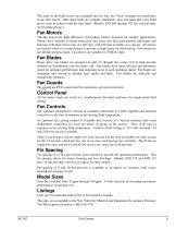
The tubes in the fluid circuit are expanded into the fins, but “float” through oversized holes in the tube sheets. Tube sheet leaks are virtually eliminated, since the tubes that carry fluid never come in contact with the tube sheet. (Models AFS 005 through 021 are conventional, non-floating design.) Fan Motors The fan motors are high efficiency, three-phase motors designed for outdoor applications. Motors have thermal overload protection and fuses and have permanently lubricated ball bearings with direct drive fans at 1140 rpm, with 830 rpm available as a special. All motors are factory-wired...
Open the catalog to page 5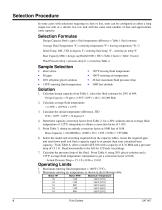
Selection Procedure In some cases with selections requiring six fans or less, units can be configured as either a long single-row unit or a shorter two row unit with the same total number of fans and approximate same capacity. Selection Formulas Design Capacity Btuh = gpm × fluid temperature difference × Table 1 fluid constant Average Fluid Temperature °F = (entering temperature °F + leaving temperature °F) / 2 Initial Temp. Diff., ITD in degrees F = entering fluid temp. °F – entering air temp °F Base Capacity Mbh = design cap Btu/h/(1000 × ITD x Table 2 factor × Table 3 factor) Fluid Pressure...
Open the catalog to page 6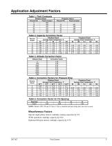
Table 2, Capacity Correction Factor Percent Glycol Table 3, Altitude Correction Factor Altitude (Feet) Correction Factor Table 4, Correction Factors for Pressure Drop Percent Glycol 0 10 20 30 40 50 Table 5, Correction Factor for Fin Spacing Fins/inch Factor NOTE: Models AFD 178 and 212 have 14 fpi as standard and their rating takes this into account. Miscellaneous Factors Special single-phase motors: multiply catalog capacities by 0.9 50 Hz operation: multiply capacity by 0.92 Optional 830-rpm motors: multiply capacity by 0.75 Fluid Coolers
Open the catalog to page 7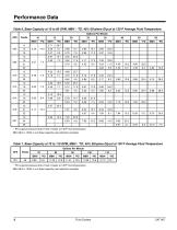
Performance Data Table 6, Base Capacity at 10 to 60 GPM, MBH / TD, 40% Ethylene Glycol at 130 °F Average Fluid Temperature * PD is glycol pressure drop in feet of water at 130°F fluid temperature. Mbh (Btuh x 1000) is unit base capacity (see selection example). Fluid Coolers
Open the catalog to page 8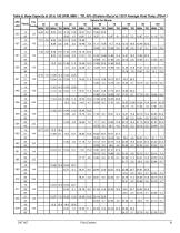
Table 8, Base Capacity at 20 to 100 GPM, MBH / ° TD, 40% Ethylene Glycol at 130° Average Fluid Temp. (PD=ft.) F AFS AFD Fluid Coolers
Open the catalog to page 9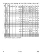
Table 9, Base Capacity at 20 to 100 GPM, MBH / ° TD, 40% Ethylene Glycol at 130° Average Fluid Temp. (PD=ft) F AFS AFD * PD is glycol pressure drop in feet of water at 130° fluid temperature. F Mbh (Btuh x 1000) is unit base capacity (see selection example). Fluid Coolers
Open the catalog to page 10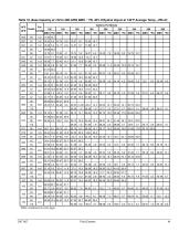
Table 10, Base Capacity at 120 to 280 GPM, MBH / ° TD, 40% Ethylene Glycol at 130° Average Temp., (PD=ft) F AFS AFD Table continued on next page. Fluid Coolers
Open the catalog to page 11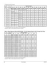
Continued from previous page. AFS * PD is glycol pressure drop in feet of water at 130° fluid temperature. F Mbh (Btuh x 1000) is unit base capacity (see selection example). Table 11, Base Capacity at 300 to 500 GPM, MBH / ° TD, 40% Ethylene Glycol at 130° Average Fluid Temp. F Gallons Per Minute * PD is glycol pressure drop in feet of water at 130° fluid temperature. F Mbh (Btuh x 1000) is unit base capacity (see selection example). Fluid Coolers
Open the catalog to page 12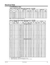
Table 13, Electrical Data, Models 023 through 212, 1140 RPM Model Fluid Coolers
Open the catalog to page 13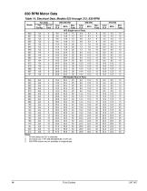
830 RPM Motor Data Table 14, Electrical Data, Models 023 through 212, 830 RPM Model Fluid Coolers
Open the catalog to page 14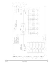
Figure 1, Typical Wiring Diagram NOTE: The controller is a Johnson A419 Electronic Temperature Control with Display. Fluid Coolers
Open the catalog to page 15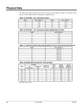
Physical Data The inlet and outlet connection size will be based on the number of feeds in the fluid cooler circuit. Use the tables below to determine connection sizes. Table 15, AFS 005 – 021, Connection Sizes Feeds Table 16, AFS 023 – 107, Connection Sizes (Single-Row of Fans) Feeds Table 17, AFD Connection Sizes (Double-Row of Fans, Dual Fluid Connections) Feeds Table 18, Model 005 through 021, Physical Data Fan Data Approx. Shipping Weight, lb. Approx Operating Weight, lb. Net weight is dry unit only. Fluid Coolers
Open the catalog to page 16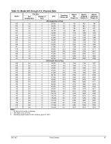
Table 19, Model 023 through 212, Physical Data Fan Data Model Approx. Shipping Weight, lb. Approx. Operating Weight, lb. Notes: 1. All fans are 30 inches in diameter. 2. Net weight is dry unit only. 3. Operating weight based on 50% ethylene glycol at 130°F. Fluid Coolers
Open the catalog to page 17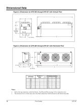
Dimensional Data Figure 2, Dimensions for AFS 005 through AFS 021 with Vertical Flow Figure 3, Dimensions for AFS 005 through AFS 021 with Horizontal Flow Inlet is the top connection, outlet the bottom. See Physical Data on page 16 for connection sizes. The electrical box is on the same end as the fluid connections with knockouts on the bottom and sides. Fluid Coolers
Open the catalog to page 18All Daikin Applied catalogs and technical brochures
 Maverick® II systems
2 Pages
 Destiny® Indoor Air Handler
28 Pages
 PreciseLine®
4 Pages
 OptiLine™
2 Pages
 CAT 413-4 Steam Coils
23 Pages
 CAT 412-6 Water Heating Coils
32 Pages
 CAT 903 Air Terminal Units
106 Pages
 Daikin Applied 2014
247 Pages
 CAT 610-1 (AGSD 140-200 tons)
88 Pages


- Liquid recirculation chiller
- Water recirculation chiller
- Touch screen HMI
- Industrial cooling system
- Air-cooled blast chiller
- Filter air purifier
- Water-cooled recirculation chiller
- Monitoring control system
- Mobile air purifier
- Industrial HMI terminal
- Pressure cooling system
- Industrial air conditioner
- Daikin air handling unit
- Floor-standing air conditioner
- Ventilation unit
- Control operator terminal
- Gas cooling system
- Handheld operator terminal
- Inverter heat pump