- Catalogs
- Daikin Applied
- CAT 413-4 Steam Coils
CAT 413-4 Steam Coils
1 /23Pages

CAT 413-4 Steam Coils
1 /23Pages
Catalog excerpts

Steam Coils
Open the catalog to page 1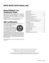
HI-F5, HI-F8 & E-F5 steam coils SelectTOOLSTM for Contractor Coils Daikin Applied offers an unmatched variety of standard fin spacings, row and circuiting combinations. For optimum coil selection, Daikin Applied's SelectTOOLSTM for Contractor Coils selection pro-gram makes it easy to select the most economical standard or special application coil to meet your job requirements. Contact your local Daikin Applied representative for a coil selection that meets the most exacting specification. Daikin steam coils are certified in accordance with the forced circulation air cooling and air heating coil...
Open the catalog to page 2
A pioneer in corrugated fin development HI-F Means High Efficiency A principal factor governing fin heat transfer efficiency is the boundary layer film of air adhering to any fin surface. This boundary layer insulates the fin, severely reducing the rate of heat exchange. The advanced rippled-corrugated HI-F design creates a state of continuous turbulence which effectively reduces the boundary layer formation. The exclusive rippled edge instantly deflects the incoming air to create initial turbulence. A succession of corrugations across the fin depth, in conjunction with the staggered tubes, increases...
Open the catalog to page 3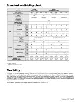
Standard availability chart STEAM (SINGLE TUBE) COIL TYPE COIL MODEL STEAM (DISTRIBUTING TUBE) 5JA SERPENTINE CIRCUIT ROWS CONNECTION LOCATION Does not apply 1 Same End FINNED LENGTH 1-1/2" INCREMENT STANDARD MAT'L MAXIMUM STD. OPERATING LIMITS ADMIRALTY BRASS * Requires 6 fins per inch or more. Flexibility Along with the standard offerings, optional materials and special configurations are provided to meet many different specifications. Extra long finned lengths, intermediate tube supports, along with a wide variety of tube wall and fin thicknesses are available. Casings can be constructed of...
Open the catalog to page 4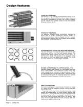
Design features PATENTED FIN DESIGNS The HI-F and E-F fin surfaces give the flexibility needed to perform at optimum efficiency. Seamless drawn copper tubes are mechanically expanded into full drawn, die-formed fin collars to provide positive metal-to-metal contact for high heat transfer efficiency and long coil life. PITCHED IN THE CASING The specially designed casing automatically provides the proper pitch for positive condensate removal resulting in reduced installation and expense. Supply and return connections are properly sized for each coil to assure optimal distribution and proper condensate...
Open the catalog to page 5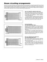
Steam circuiting arrangements Select Hl-F5, E-F5 and HI-F8 steam coils from three different circuiting arrangements: the general purpose 5SA coil, and two jet tube steam distributing styles-5JA, 8JA and 8RA coils-intended for both general and special purpose heating. While each of these arrangements has been carefully designed to serve a particular area in steam coil application, sufficient similarities are present in design and performance to render them interchangeable in many cases. Optimal fin design provides a high performing heat transfer surface while a host of exclusive features provide...
Open the catalog to page 6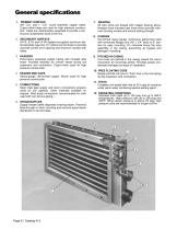
PRIMARY SURFACE 5/8” O.D. and 1” O.D. round seamless copper tubes. Cupro-nickel tubes are used for high pressure construction. Tubes are mechanically expanded to provide a continuous compression bond to the fins. BRAZING All core joints are brazed with copper brazing alloys. Headers have intruded tube holes which provide maximum brazing surface and ensure lasting strength. 2. SECONDARY SURFACE HI-F5, E-F5 and HI-F8 rippled-corrugated aluminum dieformed plate type fins. Fin collars are full drawn to provide accurate control of fin spacing and maximum contact with tubes. 8. CASINGS Die-formed heavy-gauge...
Open the catalog to page 7
Coil selection considerations Because we offer a wide variety of steam coil types, materials and fin spacings, you can obtain a very accurate selection. To obtain proper selection of each coil, the following variables should be considered. ENTERING AIR TEMPERATURE Two basic types of steam coils are offered - the single tube steam coil and the jet distributing tube steam coil. The single tube steam coil, type 5SA, is generally more economical when applied in an above freezing environment. When the entering air is near or below freezing, the jet distributing tube steam coils, types 5JA or 8JA,...
Open the catalog to page 8
TR/ITD METHOD: 1. Determine TR/ITD: TR = Lvg. Air - Ent.Air = 1,830,000 1.09 x 24,000 BASE TEMPERATURE RISE METHOD: ITD = Sat. Steam Temp. - Ent. Air Temp. Sat. Steam Temp. = 239.4 (Table 2, page 16) TR/ITD = 2. Initial Selection Enter Figure 3 at 800 FPM to determine which coil meets or exceeds a TR/ITD of 0.281. A 5SA1001C coil has a TR/lTD of 0.292. 3. Determine Condensate Loading Factor (FL) Condensate Loading = 1. Determine Air Temperature Rise TR = BTUH = 1,830,000 1.09 x CFM 1.09 x 24,000 2. Determine Steam Conversion Factor (F S) F S = 1.098 (Table 1, page 16) 3. Determine Condensate...
Open the catalog to page 9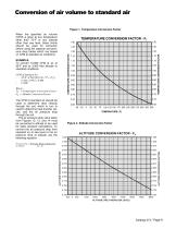
Conversion of air volume to standard air Figure 1. Temperature Conversion Factor When the specified air volume (CFM) is given at any temperature other than 70°F or any altitude other than sea level, these charts should be used for correction before using the capacity and pressure drop tables which are based on CFM at standard air conditions. TEMPERATURE CONVERSION FACTOR - FT The CFM of standard air should be used to determine face velocity through the coil, which in turn is used to determine heat transfer values, and the air pressure drop through the coil. The air pressure drop value taken from...
Open the catalog to page 10
Capacity data Figure 3. Steam Capacity Curves for HI-F5 Coils - 5SA & 5HA* CAPACITY FOR ODD FIN SPACINGS MAY BE FOUND BY INTERPOLATION 900 700 1100 STANDARD AIR FACE VELOCITY, FT/MIN. * 5J/G coils may have slightly less capacity than shown. Use SelectTOOLS TM for Contractor Coils Program for optimum selection. BASE TEMPERATURE RISE (°F) AT 5 PSIG & 0°F ENTERING AIR TR/ITD AIR TEMPERATURE RISE/DEGREE TEMPERATURE DIFFERENCE BETWEEN STEAM AND ENTERING AIR
Open the catalog to page 11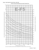
Figure 4. Steam Capacity Curves E-F5 Coils - 5SA & 5HA* CAPACITY FOR ODD FIN SPACINGS MAY BE FOUND BY INTERPOLATION .90 BASE TEMPERATURE RISE (°F) AT 5 PSIG & 0°F ENTERING AIR TR/ITD AIR TEMPERATURE RISE/DEGREE TEMPERATURE DIFFERENCE BETWEEN STEAM AND ENTERING AIR STANDARD AIR FACE VELOCITY, FT/MIN. * 5J/G coils may have slightly less capacity than shown. Use SelectTOOLSTM for Contractor Coils Program for optimum selection.
Open the catalog to page 12All Daikin Applied catalogs and technical brochures
 Maverick® II systems
2 Pages
 Destiny® Indoor Air Handler
28 Pages
 PreciseLine®
4 Pages
 OptiLine™
2 Pages
 CAT 412-6 Water Heating Coils
32 Pages
 CAT 903 Air Terminal Units
106 Pages
 Daikin Applied 2014
247 Pages
 CAT 610-1 (AGSD 140-200 tons)
88 Pages


- Daikin cooler
- Liquid recirculation chiller
- Water recirculation chiller
- Touch screen HMI
- Industrial cooling system
- Air-cooled blast chiller
- Filter air purifier
- Water-cooled recirculation chiller
- Monitoring control system
- Mobile air purifier
- Industrial HMI terminal
- Pressure cooling system
- Industrial air conditioner
- Daikin air handling unit
- Floor-standing air conditioner
- Ventilation unit
- Control operator terminal
- Gas cooling system
- Handheld operator terminal
- Inverter heat pump