- Catalogs
- Daikin Applied
- CAT 412-6 Water Heating Coils
CAT 412-6 Water Heating Coils
1 /32Pages

CAT 412-6 Water Heating Coils
1 /32Pages
Catalog excerpts
Daikin® Water Heating & High Capacity Booster Coils Types HI-F5 & E-F5
Open the catalog to page 1
HI-F5 & E-F5 water heating and high capacity booster coils SelectTOOLSTM for Contractor Coils Daikin offers a wide variety of standard fin spacings, row and circuiting combinations. For optimum coil selection, McQuay's SelectTOOLSTM for Contractor Coils selection program makes it easy to select the most economical standard or special application coil to meet your job requirements. Contact your local Daikin representative for a coil selection that meets the most exacting specification. ARI certification Daikin® water heating and booster coils are certified in accordance with the forced circulation...
Open the catalog to page 3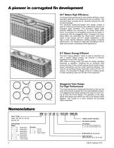
A pioneer in corrugated fin development HI-F Means High Efficiency A principal factor governing fin heat transfer efficiency is the boundary layer film of air adhering to any fin surface. This boundary layer insulates the fin, severely reducing the rate of heat exchange. The advanced rippled-corrugated HI-F design creates a state of continuous turbulence which effectively reduces the boundary layer formation. The exclusive rippled edge instantly deflects the incoming air to create initial turbulence. A succession of corrugations across the fin depth, in conjunction with the staggered tubes, increases...
Open the catalog to page 4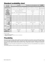
Standard availability chart COIL TYPE COIL MODEL CLEANABLE HOT WATER (REMOVABLE PLUG) SERPENTINE CIRCUIT CONNECTION LOCATION 1-1/2" INCREMENT FINNED LENGTH SPACING (FPI) DIAMETER FACE C/C TUBING COPPER STANDARD MAT'L** Copper Tubing Copper Tubing Threaded Copper Fittings OPERATING LIMITS Feature Available * .020” is a nominal tube thickness ** Optional header materials are available; consult your representative. *** Available in 6” increments. Flexibility Along with the standard offerings, optional materials and special configurations are provided to meet many different specifications. Extra...
Open the catalog to page 5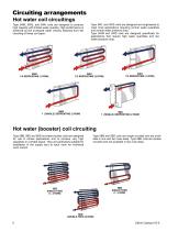
Circuiting arrangements Hot water coil circuitings Type 5WB, 5WQ, and 5WH coils are designed to produce high capacity with limited water quantity. High performance is achieved by the increased water velocity obtained from the circuiting of these coil types. Type 5WL and 5WS coils are designed and engineered to meet most applications requiring normal water quantities and normal water pressure drop. Type 5WM and 5WD coils are designed specifically for applications that require high water quantities and low water pressure drop. Hot water (booster) coil circuiting Type 5BB, 5BS and 5BD hot water...
Open the catalog to page 6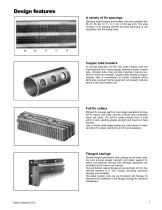
Design features A variety of fin spacings Standard water heating and booster coils are available with 06, 07, 08, 09, 10, 11, 12, 13 or 14 fins per inch. The wide variation in fin spacing permits accurate balancing of coil capacities with the design load. Copper tube headers To provide extended coil life, 5W water heating coils are manufactured from heavy-gauge seamless drawn copper tube. Intruded tube holes provide maximum brazing surface for maximum strength. Copper tubes brazed to copper headers offer a combination of similar materials which eliminates unequal thermal expansion and greatly...
Open the catalog to page 7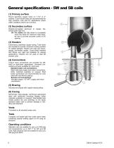
General specifications - 5W and 5B coils (1) Primary surface Round seamless copper tubes on 1-1/2" or 3" centers. Cupro-nickel tubes are recommended for high pressure coils and for applications where water conditions tend to be corrosive. (2) Secondary surface Rippled-corrugated aluminum or copper, dieformed plate type fins. 2A. Fin collars are fully drawn to completely cover the tubes for maximum heat transfer and to provide accurate control of fin spacing. (3) Headers Extra-heavy, seamless copper tubing. Tube holes are intruded to provide maximum brazing surface for added strength. Header end...
Open the catalog to page 8
Application recommendations 1. Piping should be in accordance with accepted industry standards. 2. When drainable coils are desired, tubes should be installed in a horizontal position. Use a spirit level. If the tubes cannot be installed level, special drain headers are available on request. 3. Connect the water supply to the leaving air side and the water return to the entering air side of the coil. Connecting the supply and/or return in any other manner will result in a reduced performance. 4. Hot water coils are not normally recommended for use with entering air temperatures below 40° F; however,...
Open the catalog to page 9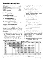
Sample coil selection Given: Assuming a 1-row type 5WB coil will meet the requirements, the proper fin series must be determined as follows: 8. Determine heat transfer value, Mt: a. Air Temp. Rise = 36.7 = .237 Ent. Water Temp. - Ent. Air Temp 200 - 45 b. Water Temp. Drop Air Temp.Rise Solution: 1. Determine coil face area: 24 x 72 = 12.0 sq. ft. 144 With values from steps a. and b. above, proceed to Figure 3, page 11, and find Mt = .33 2. Determine coil face velocity: SCFM = 6,000 = 500 FPM 12.0 Face Area Determine heat transfer value, Rft: Rows Deep = Rft x Mt x FPM 100 3. Determine air temperature...
Open the catalog to page 10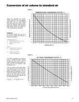
Conversion of air volume to standard air Figure 1. TEMPERATURE CONVERSION FACTOR - FT 1.25 TEMPERATURE CONVERSION FACTOR EXAMPLE: To convert 15,900 CFM of air at 95°F and at 3,000 feet altitude to standard conditions: When the specified air volume (CFM) is given at any temperature other than 70° F or any altitude other than sea level, these charts should be used for correction before using the capacity and pressure drop tables which are based on CFM at standard air conditions. TEMPERATURE CONVERSION FACTOR Where: FT = Temperature Conversion Factor from Figure 1 FA = Altitude Conversion Factor...
Open the catalog to page 11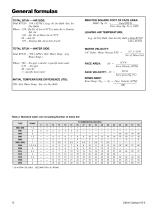
General formulas TOTAL BTUH — AIR SIDE: Total BTUH = 1.09 x SCFM x (Lvg. Air Dry Bulb -Ent. Air Dry Bulb) Where: 1.09 = (Sp Ht. of Air at 70°F) x (min./hr.) x Density Std. Air .242 = Sp. Ht. of Moist Air at 70°F 60 = min./hr. .075 = Density Std. Air in Lbs./Cu.Ft. MBH PER SQUARE FOOT OF FACE AREA: MBH / Sq. Ft. = Total BTUH Face Area (Sq. Ft.) x 1000 TOTAL BTUH — WATER SIDE: WATER VELOCITY: 5/8" Tubes: Water Velocity FPS = Total BTUH LEAVING AIR TEMPERATURE: Lvg. Air Dry Bulb = Ent.Air Dry Bulb + Total BTUH 1.09 x SCFM 500 x GPM x (Ent. Water Temp. - Lvg. Water Temp.) Where: 500 = lbs./gal. x...
Open the catalog to page 12All Daikin Applied catalogs and technical brochures
 Maverick® II systems
2 Pages
 Destiny® Indoor Air Handler
28 Pages
 PreciseLine®
4 Pages
 OptiLine™
2 Pages
 CAT 413-4 Steam Coils
23 Pages
 CAT 903 Air Terminal Units
106 Pages
 Daikin Applied 2014
247 Pages
 CAT 610-1 (AGSD 140-200 tons)
88 Pages


- Daikin cooler
- Liquid recirculation chiller
- Water recirculation chiller
- Touch screen HMI
- Industrial cooling system
- Air-cooled blast chiller
- Filter air purifier
- Water-cooled recirculation chiller
- Monitoring control system
- Mobile air purifier
- Industrial HMI terminal
- Pressure cooling system
- Daikin air handling unit
- Industrial air conditioner
- Floor-standing air conditioner
- Ventilation unit
- Control operator terminal
- Gas cooling system
- Handheld operator terminal
- Inverter heat pump