- Catalogs
- Daikin Applied
- CAT 411-7 Cooling & Evaporator Coils
CAT 411-7 Cooling & Evaporator Coils
1 /36Pages

CAT 411-7 Cooling & Evaporator Coils
1 /36Pages
Catalog excerpts

Daikin® Water Cooling & Evaporator Coils Types HI-F5 & E-F5
Open the catalog to page 1
HI-F5 & E-F5 water cooling & evaporator coils SelectTOOLSTM for Contractor Coils Daikin offers a wide variety of standard fin spacings, row and circuiting combinations. For optimum coil selection, McQuay's SelectTOOLSTM for Contractor Coils selection program makes it easy to select the most economical standard or special application coil to meet your job requirements. Contact your local Daikin representative for a coil selection that meets the most exacting specification. ARI Certification Daikin® water cooling and evaporator coils are certified in accordance with the forced circulation air cooling...
Open the catalog to page 3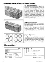
A pioneer in corrugated fin development HI-F Means High Efficiency A principal factor governing fin heat transfer efficiency is the boundary layer film of air adhering to any fin surface. This boundary layer insulates the fin, severely reducing the rate of heat exchange. The advanced rippled-corrugated HI-F design creates a state of continuous turbulence which effectively reduces the boundary layer formation. The exclusive rippled edge instantly deflects the incoming air to create initial turbulence. A succession of corrugations across the fin depth, in conjunction with the staggered tubes, increases...
Open the catalog to page 4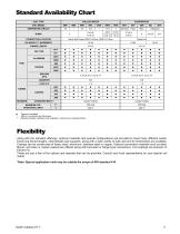
Standard Availability Chart COIL TYPE CHILLED WATER COIL MODEL SERPENTINE CIRCUIT CONNECTION LOCATION FINNED LENGTH FIN TYPE ALUMINUM FINS TUBING COPPER STANDARD MAT'L** MAXIMUM STD. OPERATING LIMITS Copper Tubing Copper Tubing Feature Available .020 is a nominal tube thickness Optional header materials are available, consult your representative Flexibility Along with the standard offerings, optional materials and special configurations are provided to meet many different needs. Extra long finned lengths, intermediate tube supports, along with a wide variety of tube wall and fin thicknesses are...
Open the catalog to page 5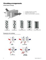
Circuiting arrangements Chilled water circuitings 5 standard serpentine circuitings Counterflow water circuits Unique or universal hand of connection Evaporator coil circuitings NOTE: See page 24 for exact number and location of coil connections.
Open the catalog to page 6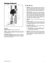
HEADERS - Extra-heavy seamless copper tubing. Tube holes are intruded to provide the maximum brazing surface for added strength. Header end caps are heavygauge, die-formed copper. Cupro-nickel headers and Monel end caps are available for special applications. CONNECTIONS - Unique hand or universal connections can be provided. Connection type must be specified. Water Coil Connections: Steel male pipe supply and return connections. Other materials available on request (red brass connections recommended on type 5W coils when used with non-ferrous piping). Evaporator Coil Connections: Male sweat...
Open the catalog to page 7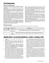
Coil Selection General Considerations The cooling process should always be plotted on a psychrometric chart to be sure that desired psychrometric changes are feasible. When selecting a coil, it should be remembered that if the required leaving wet bulb temperature is attained, the total load is satisfied and vice versa. Also, when the required leaving dry bulb temperature is met, the sensible load requirement is satisfied. A coil must meet both the total and sensible load requirement in order to achieve the conditions desired in the space to be cooled. Normally, the total load capacity is checked...
Open the catalog to page 8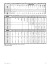
Table 1: Standard water coil circulating (number of tubes fed) - for calculating water velocity for types 5W and 5M coils FIN HEIGHT (INCHES) TYPE Table 2: Coil sizes face area in square feet FIN HEIGHT 12 15 18 FINNED LENGTH – FL (INCHES) 12 FINNED LENGTH – FL (INCHES) 72 NOTE: In addition to the standard finned lengths listed above, any required finned length can be supplied.
Open the catalog to page 9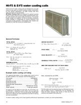
HI-F5 & E-F5 water cooling coils HI-F5 and E-F5 water cooling coils are designed for use with chilled or well water on comfort cooling, process, dehumidifying and special applications. All water cooling coils have vents and drains to aid drainability. 5W Water Cooling Coils are designed for general purpose cooling. All 5W coils have heavy-gauge seamless drawn copper tube headers with carbon steel connections. This proven header design can lengthen coil life by providing necessary header flexibility to compensate for normal expansion and contraction during operation. Intermediate drain headers...
Open the catalog to page 10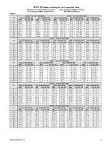
HI-F5 5/8 water cooling ari coil capacity data 80° F/67° F Entering Air Temperature 45° F Entering Water Temperature 4 Feet Per Second Water Velocity 500 FPM Air Velocity
Open the catalog to page 11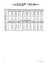
HI-F5 5/8 water cooling ari coil capacity data 80° FGPS/67° F Entering Air Temperature 45° F Entering Water Temperature 4 Feet Per Second Water Velocity 500 FPM Air Velocity Table 3. Continued 10-ROW - 24" X 48" FACE AREA FPI
Open the catalog to page 12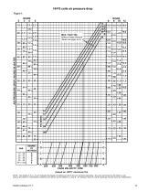
HI-F5 coils air pressure drop Figure 1. AIR PRESSURE DROP, INCHES IN WATER MAX. FACE VEL. Without Water Blowoff (Does not apply to A) (based on .0075” aluminum fin) NOTE: The letters A, B, C, D or E indicate the degree of wetness at which the coil would be operating. Dry coils are shown by the letter A, wet coils by the letter E. Intermediate conditions are shown by the letters B, C and D. Air pressure drop for odd fin spacings may be found by interpolation.
Open the catalog to page 13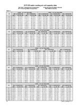
E-F5 5/8 water cooling ari coil capacity data 80° F/67° F Entering Air Temperature 45° F Entering Water Temperature 4 Feet Per Second Water Velocity 500 FPM Air Velocity Table 4. 2-ROW - 24" X 48" FACE AREA FPI
Open the catalog to page 14
E-F5 5/8 water cooling ari coil capacity data 80° F/67° F Entering Air Temperature 45° F Entering Water Temperature 4 Feet Per Second Water Velocity 500 FPM Air Velocity Table 4 - Continued 10-ROW - 24" X 48" FACE AREA FPI
Open the catalog to page 15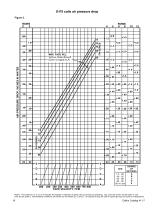
E-F5 coils air pressure drop Figure 2. AIR PRESSURE DROP, INCHES IN WATER 08 MAX. FACE VEL. Without Water Blowoff (Does not apply to A) DEGREE OF WETNESS A 1.0 - .98 B .98 - .92 C .92 - .86 D .86 - .80 E .80 or Less SHR NOTE: The letters A, B, C, D or E indicate the degree of wetness at which the coil would be operating. Dry coils are shown by the letter A, wet coils by the letter E. Intermediate conditions are shown by the letters B, C and D. Air pressure drop for odd fin spacings may be found by interpolation.
Open the catalog to page 16All Daikin Applied catalogs and technical brochures
 Maverick® II systems
2 Pages
 Destiny® Indoor Air Handler
28 Pages
 PreciseLine®
4 Pages
 OptiLine™
2 Pages
 CAT 413-4 Steam Coils
23 Pages
 CAT 412-6 Water Heating Coils
32 Pages
 CAT 903 Air Terminal Units
106 Pages
 Daikin Applied 2014
247 Pages
 CAT 610-1 (AGSD 140-200 tons)
88 Pages


- Daikin cooler
- Liquid recirculation chiller
- Water recirculation chiller
- Touch screen HMI
- Industrial cooling system
- Air-cooled blast chiller
- Filter air purifier
- Water-cooled recirculation chiller
- Monitoring control system
- Mobile air purifier
- Industrial HMI terminal
- Pressure cooling system
- Industrial air conditioner
- Daikin air handling unit
- Floor-standing air conditioner
- Ventilation unit
- Control operator terminal
- Gas cooling system
- Handheld operator terminal
- Inverter heat pump