- Catalogs
- DAEHWA E/M CO.,LTD
- cate_201205091741322
cate_201205091741322
1 /14Pages

cate_201205091741322
1 /14Pages
Catalog excerpts

s1' BLDC Motor drivers
Open the catalog to page 1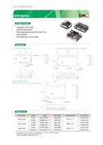
- Compact & High Power - Stable constant speed -Wide rangespeed control(100~3000 r/min) -High Reliability - Remote speed-control possible • EntertheGearratio(5,10,15,20,30,50,100,200)inthebox( □□ □ ) with in the model name. • A. is K(Combi nation GearType)orS(Round Shaft Type) • PleaserefertotheMotorandGearhead section
Open the catalog to page 2
Speed - Torque Characteristics EXH:EXH Series Shaft Type K:Combi nation GearedType Gear Ratio Number: Gear Ratio Empty: Round ShaftType - Power Supply Voltage
Open the catalog to page 3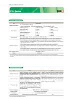
Common Specifications Speed Control Method 1. By built-in potentiometer 2. By external potentiometer 3. By DC voltage(0~5VDC) Input Signals C-MOS negative logic START/STOP input Brake input Direction of Rotation input Speed setting method Alarm reset Output Signals Open collector output External use conditions 26.4VDC, 10mA Max. Speed Signal Output(SPEED OUT) 36P/R, Alarm Signal Output(AI_ARM OUT), Direction Signal Output(DIR OUT) Protection Functions*! When the following are activated, the alarm signal will be output and the motor will come to a natural stop ■ Overload Protection: Activated...
Open the catalog to page 4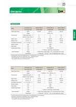
* The permissible load inertia spedified above is only applicable for round shaft type. Permissible Load Inertia for Combination Type —> Gearhead section ■ Enter the gear ratio in the box(d) with the model name. ■ The values for each item is for the motor only * The permissible load inertia spedified above is only applicable for round shaft type. Permissible Load Inertia for Combination Type—»Gearhead section Enter the gear ratio in the box(rj) with the model name. ■The values for each item is for the motor only
Open the catalog to page 5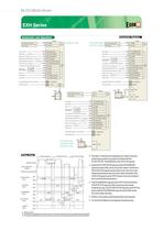
Power Supply Connection power supply Brake input [ S&'SU™^ ]- Flotation Direction Switching Input [ ]-^ Speed Setting Mode Selection Input [ §rV Alarm Reset Input [ O&'JESJ- '5V 0utput(0nly Use for Speed Setting Potentiometer] Speed Setting Speed Output- Alarm Output — Acceleration/Deceleration Time Potentiometer Power Supply Connection power supply Power Supply Connection power supply '5V Output(Only Use for Speed Setting Potentiometer] Alarm Reset Input [ rSSmUi ]- Speed Setting Mode Selection Input [ g^.'gjjjj ] - Rotation Direction Switching Input [ g^:: cow ]- Brake input [ C^LT^E**]- Direction...
Open the catalog to page 6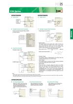
Input Signal Circuit Driver Internal Circuit ■ Example of Input Circuit Connection Control by Small Capacity Relay, Switch. Internal External INT.VR/EXT Input ALARM-RESET Input SPEED Output Transistor Output Type Driver Internal Circuit C-MOS Output Type Driver Internal Circuit Output Signal Circuit Driver Internal Circuit Example of Output Circuit Connection Output Signal Connections Driver Internal Circuit Speed Output The system outputs pulse signals (with a width of 0.3ms) at a rate of 36 pulses per rotation of the motor output shaft, synchronized with the motor drive. You can measure the...
Open the catalog to page 7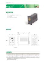
- Stable constant speed - Wide range speed control(100~2000 r/min) - High Reliability - Remote speed-control possible ■ A is K(Combination Gear Type) or S(Round Shaft Type) ' PleaserefertotheMotorandGearhead section
Open the catalog to page 8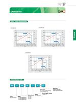
Speed - Torque Characteristics EXU:EXU Series Shaft Type K: Combination Geared Type Power Supply Voltage Number:Gear Ratio Empty: Round ShaftType
Open the catalog to page 9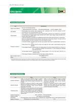
BLDC Motor driver Common Specifications *1 With the EXU Series the motor speed cannot be controlled in applications where the motor shaft is turned by the load, as in lowering operations. Also, the motor will slop naturally if the load exceeds the permissible load inertia or the overvoltage protection function is activated during load lowering operations. General Specifications
Open the catalog to page 10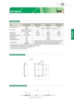
* The permissible load inertia spedified above is only applicable for round shaft 1ype. Permissible Load Inertia for Combination Type —»Gearhead Section ■ Enter the gear ratio in the boxflU) with the model name. ■ The values for each item is for the motor only Control Unit Panel Cut-Out Power Supply Cable(lncluded) MOTOR POWERS CONTROL UNIT
Open the catalog to page 11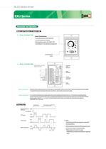
BLDC Motor driver ■ Front of Control Unit Turning the potentiometer clockwise causes the speed to increase. Speed setting range is 100~2000 r/min. ThesettingisO r/min atthetimeof shipment SPEED CONTROL UNIT I DAEHWA ELECTRIC MACHINERY CO.,LTD, input/output correction signal terminals Motor Connection lnsertthemotorcableconnectorintothemotorconnector(MOTOR)onthemdriverJnsertituntilaclicksoundisaudible. Toextendthedistance between the motoranddriver,use an optional extension cable. Power Connection Connectthe included powersupply cabletothe powersupplyterminal of thedriver. Connectthe red and blacklead...
Open the catalog to page 12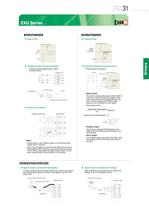
Input Signal Circuit Driver Interna] Circuit ■ Example of Input Circuit Connection Control by Small Capacity Relay, Switch, Connected at trie COM of I/O terminal EXTERNAL CONTROLLER CONTROL UNIT shield wire • Output signal is open collector output, so an external power • Use a power supply of no more than 26.4VDC and connect a limit resistance (R) so that the ouput current does not exceed 10mA. When using neither the speed output function nor the alarm output function, this connection Is not required. Output Siqnal Circuit Driver Internal Circuit Example of Output Circuit Connection * Output...
Open the catalog to page 13
Below is not all models we can make. It is possible to make motor as per customer requirement.
Open the catalog to page 14All DAEHWA E/M CO.,LTD catalogs and technical brochures
 SPEED CONTROL INDUCTION MOTORS
20 Pages
 cate_201205091303172
14 Pages
 cate_201205091303422
18 Pages
 cate_201205091304562
11 Pages
 cate_201205091301262
18 Pages
 cate_201205091259402
23 Pages
 cate_201205091712002
6 Pages
 cate_201205091709592
4 Pages
 cate_201205091709302
8 Pages
 cate_201205091659272
17 Pages
 cate_20120
8 Pages
 cate_2
14 Pages
 DC,BLDC MOTOR
84 Pages

Archived catalogs
 AC BRAKE,TORQUE MOTOR
88 Pages
- LIMING pump
- LIMING industrial pump
- LIMING electric pump
- LIMING stationary pump
- Electromotor
- Seawater pump
- Self-priming pump
- DC electromotor
- Synchronous motor
- Alternating current motor
- Multipole motor
- Diaphragm pump
- LIMING gear-motor
- Asynchronous motor
- LIMING planetary gear reducer
- LIMING coaxial gear reducer
- EC motor
- Three-phase motor
- LIMING precision gear reducer
- 24 V motor