


MCE/C

MCE/C
The document introduces the MCE/C series inverters by DAB Pumps, designed for use with circulator pumps. These inverters are noted for their ease of use, power efficiency, and simple installation. They are equipped with dual microprocessor architecture for enhanced efficiency and reliability.
Specifications
The MCE/C inverters are available in various models, each supporting different power capacities:
- MCE/C 11, 15, 22: For three-phase pumps up to 3HP - 2.2kW
- MCE/C 30, 55: For three-phase pumps up to 7.5HP - 5.5kW
- MCE/C 110, 150: For three-phase pumps up to 20HP - 15kW
Energy Efficiency
The document highlights the energy-saving capabilities of the MCE/C inverters. By reducing motor speed, significant power savings can be achieved due to the cubic relationship between power consumption and rpm. This also extends the pump's lifespan by reducing mechanical stress.
Operating Modes
The MCE/C inverters support various control modes:
- Constant Differential Pressure Control Mode (ΔP-c): Maintains constant differential pressure as flow rate varies.
- Constant Curve Control Mode: Keeps rotation speed constant, adjustable via the control panel.
- Constant Curve Control with Remote Analogue Signal: Adjusts rotation speed based on a remote signal.
Installation and Connectivity
The inverters can be mounted on the motor base, either vertically or horizontally. Two kits are available for assembly: tie-rods and fan cover kits. The inverters support twin operation, allowing up to two pumps to be connected and controlled in tandem.
Conclusion
The MCE/C inverters by DAB Pumps offer advanced features for efficient and reliable pump operation, with significant energy savings and extended pump life. They are versatile in installation and operation, making them suitable for various heating system configurations.
Catalog excerpts
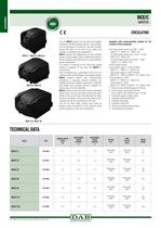
ELECTRONICS MCE/C INVERTER CIRCULATING MCE/C 11 - MCE/C 15 - MCE/C 22 MCE/C 30 - MCE/C 55 The new MCE/C inverters are the latest technological challenge in the DAB inverters universe. They constitute the new generation of inverters for use with circulator pumps and stand out for ease of use, power, and simplicity of installation and management. MCE/C inverters are designed for use with circulator pumps to enable simple control of differential pressure, thereby adapting pump performance to match effective system requirements. The solution of mounting on the motor base greatly simplifi es installation of the pump with MCE/C in minimal times. Ease of programming is guaranteed by the use of an interface similar to DAB Dialogue and a graphic display. MCE/C inverters feature dual microprocessor architecture to guarantee maximum efficiency and reliability. Sturdy and reliable construction is combined with modern and innovative styling to complete the product also in terms of aesthetics. MCE/C inverters protect the pump thanks to integrated safety devices. They are also able to prolong the useful lifetime of the pump thanks to the elimination of water hammer and rotation of the pump at the minimum rpm necessary to meet the requirements of the user. Last but not least, these inverters save power by keeping pump consumption to the minimum levels strictly necessary to meet user requirements. Equipped with communication module for the creation of twin pumpsets. • For three-phase pumps up to 3HP - 2,2kW (MCE/C 11 – MCE/C 15 – MCE/C 22). For three-phase pumps up to 7,5 HP - 5.5 kW (MCE/C 30 – MCE/C 55). For three-phase pumps up to 20HP – 15kW ( MCE/C 110 – MCE/C 150). • OLED graphic display. • Input power supply 1 x 230V 50-60Hz (MCE/C 11 – MCE/C 15 – MCE/C 22). Input power supply 3 x 400V 50-60Hz (MCE/C 30 – MCE/C 55 MCE/C 110 – MCE/C 150). • Pump voltage 3 x 230V (MCE/C 11 – MCE/C 15 – MCE/C 22). Pump voltage 3 x 400V (MCE/C 30 – MCE/C 55 MCE/C 110 – MCE/C 150). • Electric pump nominal frequency 50-200 Hz. • Control range in accordance with the sensor utilised, with standard range 1-24 Bar. • Protections against voltage surges. • Adjustable overload protection. • Extended connectivity. • Protection rating: IP55. • Short circuit between output phases. • Overtemperature protection. MCE/C 110 - MCE/C 150 TECHNICAL DATA CODE NOMINAL MOTOR POWER kW MAX NOMINAL MOTOR CURRENT A MIN NOMINAL MOTOR CURRENT A VOLTAGE 50 Hz PUMP VOLTAGE 50 Hz MOTOR FRAME MCE/C 11 60144656 1.1 6.5 1.0 Single-phase 1x230 Three-phase 3x230 71 80 MCE/C 15 60144657 1.5 8,0 1.0 Single-phase 1x230 Three-phase 3x230 90 MCE/C 22 60144659 2.2 10.5 1.0 Single-phase 1x230 Three-phase 3x230 90 100 MCE/C 30 60144660 3 7,5 2.0 Three-phase 3x400 Three-phase 3x400 100 MCE/C 55 60144662 5,5 13,5 2.0 Three-phase 3x400 Three-phase 3x400 112 132 MCE/C 110 60144664 11.0 24 2.0 Three-phase 3x400 Three-phase 3x400 132 160 MCE/C 150 60144665 15.0 32 2.0 Three-phase 3x400 Three-phase 3x400 160 MODEL DAB PUMPS reserves the right to make modifications without notice
Open the catalog to page 1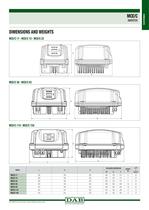
DAB PUMPS reserves the right to make modifications without notice
Open the catalog to page 2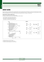
ELECTRONICS MCE/C INVERTER ENERGY SAVING Reducing motor speed, even marginally, can lead to an appreciable reduction in power consumption because the absorbed power of an electric motor is proportional to the rpm cubed. For example, a pump powered by the mains that runs at approximately 2950 rpm, will run approximately 20% slower (i.e. at 2360 rpm) when fed with a 40 Hz supply, leading to a saving of 40% in terms of absorbed power. The motor speed reduction increases pump life signifi cantly, thanks to the reduction of mechanical stress. Pump performance in relation to variations in rpm Pump...
Open the catalog to page 3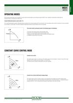
INVERTER OPERATING MODES All the functions listed below can be consulted by all users (even the least skilled) by just scrolling through the MCE/C menu. Calibration and parameter modifi cation are protected functions, permitted only to skilled users. Constant differential pressure control mode ΔP-c ΔP-c control mode keeps the system’s differential pressure constant at the H value set (setp) as the fl ow rate varies. This is the standard control mode, for normal use. It can be set directly from the MCE/C’s control panel. The inverter maintains the differential pressure (H setp) constant as the...
Open the catalog to page 4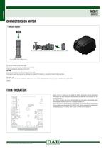
ELECTRONICS MCE/C INVERTER CONNECTIONS ON MOTOR 1 Hydraulic diagram The MCE is installed on the motor base. The inverter can operate both vertically and horizontally. 2 kits are available for assembly on the motor: Tie-rods: These are connected to the MCE dissipator and fan cover. They require a solid fan cover able to withstand the weight of the inverter, i.e. secured by means of bolts or screws. Fan cover kit: The fan cover kit is used in all situations where the fan cover is not sufficiently solid or strong enough to withstand the weight of the inverter. TWIN OPERATION Groups of up to 2 pumps...
Open the catalog to page 5All DAB catalogs and technical brochures
 NKM-GE / NKP-GE 2026
81 Pages
 UNI EN 12845 FIRE-FIGHTING SETS
16 Pages
 EVOSTA SIMPLY RELIABLE
20 Pages
 SWIMMING POOL PUMPS
20 Pages
 ADAC
ADAC4 Pages
 ACTIVE DRIVER
1 Page


Archived catalogs
 AC 65-80-110
2 Pages
 MCE/P
MCE/P5 Pages
 E-BOX
E-BOX1 Page
 SMART PRESS
1 Page
 new products 2010
4 Pages
 ST_NKM-GE_NKP-GE
28 Pages