- Catalogs
- CURTISS-WRIGHT
- WCS-134143
- Company
- Products
- Catalogs
- News & Trends
- Exhibitions
WCS-134143
1 /5Pages

WCS-134143
1 /5Pages
Catalog excerpts

CONTROLS WCS-134143Rev c - April 8,2008Non-contact Rotary Position Sensor Features • Dual Ratiometric APS output • Independent, Isolated APS circuits • IP66 Sealed • Highly EMI resistant (SAE J1113) • +5V Operation • Integral Preload Spring • Integral Metripack 150 Series Connector • Protected against Electrical Misconnection Applications • Truck Throttle Position Sensor Description: This device is a solid-state rotary position sensor that provides a dual linear output voltage proportional to absolute shaft rotation in either direction from a reference angle. It operates from +5V power typically supplied by a vehicle engine control unit (ECU). This device’s two outputs are independent and electrically isolated, supporting the implementation of highly fault tolerant and reliable systems. Mating Connector Packard Electric “Metri-Pack” Series 150 Housing p/n: 12066317 Terminal p/n: 12103881 Williams Controls Phone (503) 684-8600 Portland, OR. 97224 and Proprietary Email info@_wmco.co
Open the catalog to page 1
Absolute Maximum Ratings APS Circuits Supply Voltage (VCC1, VCC2) Output Current (APS1, APS2 output) APS1,2 short circuit duration to ground APS1,2 short circuit duration to VCC Whole Sensor Operating Temperature Storage Temperature Operation of this device beyond absolute maximum ratings may result in permanent damage. Electrical Specifications Over -40°C to +85°C temperature range, VCcx=5.0V unless noted Mechanical Specifications Williams Controls 2 Phone (503) 684-8600 Portland, OR. 97224 and Proprietary Email info@_wmco.
Open the catalog to page 2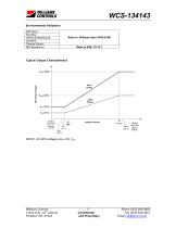
Environmental Validation Typical Output Characteristics NOTE: All APS voltages are ± 2% Vref. Williams Controls 3 Phone (503) 684-8600 Portland, OR. 97224 and Proprietary Email info@_wmco.com
Open the catalog to page 3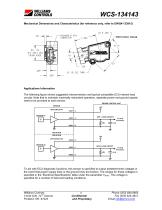
WCS-134143 Mechanical Dimensions and Characteristics (for reference only, refer to DWG# 133915) Applications Information The following figure shows suggested interconnection and typical compatible ECU internal load circuits. Note that to maintain maximally redundant operation, separate power and ground signals need to be provided to each sensor. ENGINE CONTROL UNIT SENSOR APS CIRCUIT #1 APS 1 LOAD CIRCUIT To ECU Processor 47K ISOLATION ISOLATION APS CIRCUIT #2 APS 2 LOAD CIRCUIT To ECU Processor 47K To aid with ECU diagnostic functions, this sensor is specified to output predetermined voltages...
Open the catalog to page 4
Referenced Documents: • Williams Controls DWG # 133382 • Williams Controls Specification # WDS-010B • SAE J1113-1 - Electromagnetic Compatibility Measurement Procedures and Limits for Components of Vehicles, Boats, and Machines Revision History Williams Controls 5 Phone (503) 684-8600 Portland, OR. 97224 and Proprietary Email info@_wmco.com
Open the catalog to page 5All CURTISS-WRIGHT catalogs and technical brochures
 S-Drive
2 Pages
 AES-350
18 Pages
 AES-349
25 Pages
 Industrial Division
8 Pages
 Transmission Shifter
2 Pages
 SBW
SBW3 Pages
 newVSI Brochure
2 Pages
 Multi-Function Grip
2 Pages
 SCM100
3 Pages
 wm-67
wm-672 Pages
 wm-672
2 Pages
 wm-674
1 Page
 wm-68a
2 Pages
 wm-762
2 Pages
 wm-763
2 Pages
 wm-764
2 Pages
 WM-777
2 Pages
 WM-782
3 Pages
 WM-783
3 Pages
 WM 784
2 Pages
 wm-80
wm-802 Pages
 WCS-133284
5 Pages
 WM 81
WM 812 Pages
 Tilt Position Sensor
4 Pages
 Industrial Group
4 Pages
 Sealed Tilt Sensor STT280
2 Pages
 Sealed Tilt Sensor STT500
2 Pages
 Aerial Work Platforms
4 Pages
 AES-204
13 Pages
 ML1951
1 Page
 ML1441 AC
1 Page
 Diagnostic Test Tool
2 Pages
 WM526
WM5262 Pages
 CW-IG-Overview Brochure
8 Pages
 JC050
JC0502 Pages
 JC040
JC0402 Pages
 WM547 Rotary hand control
2 Pages
 WM535 Lever hand control
2 Pages
 C7 Hydraulic Lever
2 Pages
 C6 Hydraulic Lever
2 Pages
 RF15 Series
2 Pages
 RF11 Series
2 Pages
 PGFM3000 Series
3 Pages
 PGF8000 Series
4 Pages
 PGF7000
1 Page
 PGF3000 Series
4 Pages
 CW-IG-Overview
8 Pages
 CW-IG-On-Highway
4 Pages
 CW-IG-Medical Mobility
4 Pages
 CW-IG-Industrial
4 Pages
 CW-IG-Construction
4 Pages
 PGFX3000 Series
2 Pages
 PGFM8000 SERIES
4 Pages
 On-Highway
4 Pages
 GK1037
1 Page
 GK0730
1 Page
 Permanent Magnet
1 Page
 GD1444
1 Page
 D-Frame Solenoid
1 Page
 CW-IG-Agriculture
4 Pages
 SRH220DR
2 Pages
 STT280
2 Pages
 CW-IG-Material Handling
4 Pages
 C3-CE AC Motor Controller
2 Pages
 C3-36V - AC Motor Controller
2 Pages
 WM531 Remote sensor control
2 Pages
 WM526 Electronic floor pedal
2 Pages
 WM537 Electronic floor pedal
2 Pages
 WM558 Electronic floor pedal
2 Pages
 SRS Sealed Rotary Sensors
8 Pages
 STT series Sealed Tilt Sensors
12 Pages
 Holding Magnets
2 Pages
 Digital Panel Indicators
8 Pages


Archived catalogs
 ICS100 IN-CYLINDER SENSORS
8 Pages
- Technology switch
- Motor controller
- Linear position transmitter
- Control pedal
- Displacement transducer
- Single pedal pedal
- Electronic pedal
- Rotary electric switch
- Linear displacement sensor
- Solenoid
- Analog position transducer
- IP67 switch
- DC motor controller
- No-contact position sensor
- Potentiometer
- Magnetic position sensor
- Analog displacement transducer
- Manual potentiometer
- Industrial position sensor