- Catalogs
- CURTISS-WRIGHT
- AES-349
- Company
- Products
- Catalogs
- News & Trends
- Exhibitions
AES-349
1 /25Pages

AES-349
1 /25Pages
Catalog excerpts

CURTISS -WRIGHT Industrial Group - Arens Controls Industrial Division 3602 N Kennicott Ave Arlington Heights, IL 60004, USA T: +1.847.844.4700 www.cw-industrial.com EAR EXPORT CONTROLLED: This document contains technology subject to the US Export Administration Regulations (EAR). Transfer of this data by any means to a foreign person or foreign entity, whether in the US or abroad may require a license from the US Department of Commerce. Diversion contrary to US law is prohibited. Violations of these export laws and regulations are subject to severe civil and criminal penalties.
Open the catalog to page 1
AES-349 SBW II Installation Instructions TABLE OF CONTENTS …………………………………………………………………………………………………………………………..
Open the catalog to page 2
SECTION 1 HORIZONTAL ACTUATOR FOR ALLISON 1000/2000 TRANSMISSION EAR EXPORT CONTROLLED: This document contains technology subject to the US Export Administration Regulations (EAR). Transfer of this data by any means to a foreign person or foreign entity, whether in the US or abroad may require a license from the US Department of Commerce. Diversion contrary to US law is prohibited. Violations of these export laws and regulations are subject to severe civil and criminal penalties. AES-349
Open the catalog to page 3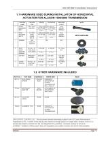
EAR EXPORT CONTROLLED: This document contains technology subject to the US Export Administration Regulations (EAR). Transfer of this data by any means to a foreign person or foreign entity, whether in the US or abroad may require a license from the US Department of Commerce. Diversion contrary to US law is prohibited. Violations of these export laws and regulations are subject to severe civil and criminal penalties.
Open the catalog to page 4
1.3 INSTALLATION PROCEDURE FOR HORIZONTAL ACTUATOR FOR ALLISON 1000/2000 TRANSIMISSION This is the Initial Installation Procedure for a new Shift By Wire Horizontal Actuator. NOTE: If this is not a “first time” installation or a replacement of a new actuator, please refer to Curtiss-Wright Arens Controls AES-350 Re-Calibration Procedure. WARNING If the transmission is installed in a chassis, do the following: a. b. c. d. Park the vehicle on level ground. Set the emergency brake. Chock/block the tires to prevent the vehicle from moving unexpectedly. Turn off the engine. FAILURE TO FOLLOW THESE...
Open the catalog to page 5
AES-349 SBW II Installation Instructions 2. Remove the 2 bolts from the rear transmission cover (these will be used as side mounted bolts) as shown in Figure #1-2. 3. Using the pre-installed Alignment tool align the SBW II Actuator with the Shift Shaft as shown. Insert the Alignment tool (TN4002) over the Shift Shaft until the holes on the rear transmission cover align with the holes on the Actuator. As shown in Figure #1-3. Continue supporting the actuator until next step is completed. Figure #1-3 4. Loosely install 2 rear cover bolts removed in step 2. Refer to Figure #1-4. LOOSELY SECURE IN...
Open the catalog to page 6
5. Place the Round Blue Space with 2 grooves (MT1317), included in the installation kit between the SBW Actuator and the Transmission. Refer to Figure #1-5. 6. Place the M8 Regular Washer on top of the SBW Actuator Bracket. Insert the Front Mounting Bolt through the Washer, Bracket, and Blue Spacer (Previously installed). Secure and Tighten as per Allison Transmission Specification (19.5 ft-lbs). As per Figure #1-6 FRONT MOUNTING BOLT Figure #1-6 TORQUE TO ALLISON TRANSMISSION SPECIFICATION 19.5 ft-lbs. EAR EXPORT CONTROLLED: This document contains technology subject to the US Export Administration...
Open the catalog to page 7
7. Secure and tighten the two previously installed Rear Mounted Bolts as per Allison Transmission Specification (41.5 ft-lbs). See Figure #1-7. REAR MOUNTED BOLTS (STEP 4) TORQUE TO ALLISON TRANSMISSION SPECIFICATION (41.5 ft-lbs). Figure #1-7 8. Remove and DISCARD the TN4002 Mounting Tool, as well as the screw securing it in place. See Figure #1-8. TN4002 ALIGNMENT TOOL (REMOVE & DISCARD) SCREW (REMOVE & DISCARD) Figure #1-8 9. Insert the Shift Shaft Adapter (FT1406) into the SBW Actuator (do NOT add grease/lube) to link up with the Shift Shaft that is coming off the Allison Transmission (Figure...
Open the catalog to page 8
AES-349 SBW II Installation Instructions 10. Insert and secure the Shift Shaft Adapter Screws (X 4) (Figure #1-10) through the slots in the Shift Shaft Adapter. Tighten the screws to 20 in-lbs. It is recommended that this is done in a “crisscross” pattern to avoid binding as per Figure #1-11. SHIFT SHAFT ADAPTER BOLTS TORQUE TO 20 IN-LBS. TIGHTEN IN A CRISS CROSS PATTERN Figure #1-11 11. Insert CAP Nut Inside the Shift Shaft Adapter Opening (do NOT add grease/lube), and Secure in Place by applying a torque of 40 in-lbs, as shown in Figure #1-12. CAP NUT INSERT AND TORQUE TO 40 IN-LBS. Figure...
Open the catalog to page 9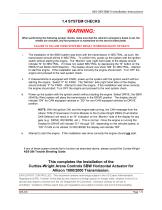
WARNING: When performing the following system checks, make sure that the vehicle’s emergency brake is set, the wheels are chocked, and foot pressure is maintained on the service brake pedal. FAILURE TO FOLLOW THESE STEPS MAY RESULT IN SERIOUS INJURY OR DEATH. The installation of the SBW system was done with the transmission in NEUTRAL; as such, the transmission should still be in NEUTRAL. To confirm this, power-up the system with the ignition switch without starting the engine. The “Monitor” side (right hand side) of the display should indicate “N” for NEUTRAL. If it does not, select NEUTRAL...
Open the catalog to page 10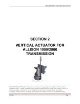
SECTION 2 VERTICAL ACTUATOR FOR ALLISON 1000/2000 TRANSMISSION EAR EXPORT CONTROLLED: This document contains technology subject to the US Export Administration Regulations (EAR). Transfer of this data by any means to a foreign person or foreign entity, whether in the US or abroad may require a license from the US Department of Commerce. Diversion contrary to US law is prohibited. Violations of these export laws and regulations are subject to severe civil and criminal penalties. AES-349
Open the catalog to page 11All CURTISS-WRIGHT catalogs and technical brochures
 S-Drive
2 Pages
 AES-350
18 Pages
 Industrial Division
8 Pages
 Transmission Shifter
2 Pages
 SBW
SBW3 Pages
 newVSI Brochure
2 Pages
 Multi-Function Grip
2 Pages
 SCM100
3 Pages
 wm-67
wm-672 Pages
 wm-672
2 Pages
 wm-674
1 Page
 wm-68a
2 Pages
 wm-762
2 Pages
 wm-763
2 Pages
 wm-764
2 Pages
 WM-777
2 Pages
 WM-782
3 Pages
 WM-783
3 Pages
 WM 784
2 Pages
 wm-80
wm-802 Pages
 WCS-133284
5 Pages
 WM 81
WM 812 Pages
 WCS-134143
5 Pages
 Tilt Position Sensor
4 Pages
 Industrial Group
4 Pages
 Sealed Tilt Sensor STT280
2 Pages
 Sealed Tilt Sensor STT500
2 Pages
 Aerial Work Platforms
4 Pages
 AES-204
13 Pages
 ML1951
1 Page
 ML1441 AC
1 Page
 Diagnostic Test Tool
2 Pages
 WM526
WM5262 Pages
 CW-IG-Overview Brochure
8 Pages
 JC050
JC0502 Pages
 JC040
JC0402 Pages
 WM547 Rotary hand control
2 Pages
 WM535 Lever hand control
2 Pages
 C7 Hydraulic Lever
2 Pages
 C6 Hydraulic Lever
2 Pages
 RF15 Series
2 Pages
 RF11 Series
2 Pages
 PGFM3000 Series
3 Pages
 PGF8000 Series
4 Pages
 PGF7000
1 Page
 PGF3000 Series
4 Pages
 CW-IG-Overview
8 Pages
 CW-IG-On-Highway
4 Pages
 CW-IG-Medical Mobility
4 Pages
 CW-IG-Industrial
4 Pages
 CW-IG-Construction
4 Pages
 PGFX3000 Series
2 Pages
 PGFM8000 SERIES
4 Pages
 On-Highway
4 Pages
 GK1037
1 Page
 GK0730
1 Page
 Permanent Magnet
1 Page
 GD1444
1 Page
 D-Frame Solenoid
1 Page
 CW-IG-Agriculture
4 Pages
 SRH220DR
2 Pages
 STT280
2 Pages
 CW-IG-Material Handling
4 Pages
 C3-CE AC Motor Controller
2 Pages
 C3-36V - AC Motor Controller
2 Pages
 WM531 Remote sensor control
2 Pages
 WM526 Electronic floor pedal
2 Pages
 WM537 Electronic floor pedal
2 Pages
 WM558 Electronic floor pedal
2 Pages
 SRS Sealed Rotary Sensors
8 Pages
 STT series Sealed Tilt Sensors
12 Pages
 Holding Magnets
2 Pages
 Digital Panel Indicators
8 Pages


Archived catalogs
 ICS100 IN-CYLINDER SENSORS
8 Pages
- Technology switch
- Position transducer
- Motor controller
- Linear position transmitter
- Control pedal
- Displacement transducer
- Single pedal pedal
- Electronic pedal
- Rotary electric switch
- Linear displacement sensor
- Solenoid
- Analog position transducer
- IP67 switch
- DC motor controller
- No-contact position sensor
- Potentiometer
- Magnetic position sensor
- Analog displacement transducer
- Manual potentiometer
- Industrial position sensor