- Catalogs
- CURTISS-WRIGHT
- AES-204
- Company
- Products
- Catalogs
- News & Trends
- Exhibitions
AES-204
1 /13Pages

AES-204
1 /13Pages
Catalog excerpts

AES-204 RevB - SBW & SBW II Re-Calibration Procedure 4-26-2013 Shift By Wire (SBW & SBW II) Actuator For Allison 1000 - 2000 Series Transmissions Actuator Re-Calibration Instructions Property of Arens Controls - Confidential Information Cover
Open the catalog to page 1
AES-204 RevB - SBW & SBW II Re-Calibration Procedure 4-26-2013 Fastener Name & Number Actuator Re-Calibration Instructions Property of Arens Controls - Confidential Information Page 1 of 12
Open the catalog to page 2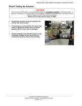
AES-204 RevB - SBW & SBW II Re-Calibration Procedure 4-26-2013 Bench Testing the Actuator: CAUTION: Do not connect the Actuator to a power supply unless it is completely installed on the transmission. If power is connected to an Actuator that is not completely installed on the transmission, the sensor will not function properly and the motor may be damaged. Failure to do so may result in injury or death. • The Actuator should not be removed from the vehicle and “bench tested”. If the Actuator is removed from the vehicle and power is applied the sensor will not function properly and the motor...
Open the catalog to page 3
AES-204 RevB - SBW & SBW II Re-Calibration Procedure 4-26-2013 There are two important points to note before re-calibrating: 1) Does the Horizontal or Vertical orientation matter? Horizontal Mounting Vertical Mounting The Procedure is the same for the Horizontal and Vertical Mounted Actuators. When there is a variation or modification in the procedure, the steps are clearly identified as ‘Horizontal Mount’ or ‘Vertical Mount’. 2) Some Allison Transmissions, known as Pre-Gen 4 Models, have an external Neutral-Start-Backup (NSBU) Assembly. Will this impact the Re-Calibration Procedure? No, you...
Open the catalog to page 4
AES-204 RevB - SBW & SBW II Re-Calibration Procedure 4-26-2013 Re-Calibration Procedure This is the SBW Re-Calibration Procedure for actuators that are already installed onto vehicles. Note: If this is a “first time” installation or a replacement of a new actuator, please refer to Arens Controls AES-203 Installation Procedure. WARNING If the transmission is installed in a chassis, do the following: a) Park the vehicle on level ground. b) Set the emergency brake. c) Chock/block the tires to prevent the vehicle from moving unexpectedly. d) Turn off the engine. Failure to follow these steps could...
Open the catalog to page 5
AES-204 RevB - SBW & SBW II Re-Calibration Procedure 4-26-2013 3. Loosen and remove the cap nut, as shown in Figure #3, and set aside. Figure #3 4. Remove these four socket head cap screws that hold the Shift Shaft Adapter in place, as shown in Figure #4. If the Shift Shaft Adapter is stuck on the Transmission Selector Shaft, use two long #10-32 screws (not supplied) to help with removal. Insert the two long #1032 screws into these holes on the Shift Shaft Adapter (see Illustration #1). The screws will act as a “puller”, and help remove the Shift Shaft Adapter from the Transmission Selector Shaft....
Open the catalog to page 6
AES-204 RevB - SBW & SBW II Re-Calibration Procedure 4-26-2013 WARNING Before moving on to the next part of the Re-Calibration Procedure, be sure that you have: a) Parked the vehicle on level ground. b) Set the emergency brake. c) Chocked/blocked the tires to prevent the vehicle from moving unexpectedly. d) Turned off the engine. Failure to follow these steps could result in serious injury or death. 5. Move up into the cab of the vehicle and turn the ignition ON, but do not engage the starter, leaving the engine OFF. Select NEUTRAL, then REVERSE, then NEUTRAL again. This will ensure that the...
Open the catalog to page 7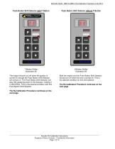
AES-204 RevB - SBW & SBW II Re-Calibration Procedure 4-26-2013 Push Button Shift Selector with P Button Push Button Shift Selector without P Button The engine should turn off when the ignition is turned off, though the Push Button Shift Selector will remain on. The Push Button Shift Selector will stay ON supplying power to the Actuator, holding it in NEUTRAL. This is the desired condition with this Push Button Shift Selector. Both the engine and the Push Button Shift Selector should turn off when the key is turned off. This is the desired condition for this shift selector. The Re-Calibration...
Open the catalog to page 8
AES-204 RevB - SBW & SBW II Re-Calibration Procedure 4-26-2013 Horizontal Mount – Loosen Mounting Bolts Vertical Mount – Loosen Mounting Bolts Figure #5a 10. Loosen the 3 bolts that hold the actuator to the transmission 1 to 3 turns. These bolts include the 2 rear cover bolts and the single front bolt. 11. Wiggle the actuator to make sure that it is loose. 12. Press the SBW Actuator Alignment Tool into the Actuator until it is flush with the actuator face. Figure #5b 10. Loosen the 4 bolts that hold the actuator to the transmission 1 to 3 turns. These bolts include the 2 rear-cover bolts and...
Open the catalog to page 9
AES-204 RevB - SBW & SBW II Re-Calibration Procedure 4-26-2013 These steps apply to both Horizontal and Vertical Mount Systems 15. Remove the SBW Actuator Alignment Tool and set aside. When removing the Alignment Tool make sure that the Actuator does not move. Lube the O-Ring on the outer face of the Actuator 16. Place a long #10-32 screw into one of the slotted holes in the lost motion wheel, shown in Figure #7a. Grasp the head of the socket head cap screw with a pair of pliers and pull the lost motion wheel outward; it should move outward above 1/8” to 3/16”. This places the actuator into the...
Open the catalog to page 10
AES-204 RevB - SBW & SBW II Re-Calibration Procedure 4-26-2013 Horizontal Mount, Shift Shaft Adapter with or without the NSBU Assembly Vertical Mount, Shift Shaft Adapter with or without the NSBU Assembly 17. Lube the O-ring on the Shift Shaft Adapter. Align the witness marks on the Shift Shaft Adapter with the witness marks on the actuator housing. Use the single groove witness mark on the Shift Shaft Adapter as shown in Figure #8a. Place the shift shaft adapter into the center of the actuator, shown in Figure #8b. Be sure that the Shift Shaft Adapter properly engages the end of Selector Shaft...
Open the catalog to page 11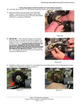
AES-204 RevB - SBW & SBW II Re-Calibration Procedure 4-26-2013 These steps apply to both Horizontal and Vertical Mount Systems 18. Insert the (Qty 4) #10-32 x ½” long Socket Head Cap Screws into the Shift Shaft Adapter. 19. Place your thumb over the center of the Shift Shaft Adapter. Press the Shift Shaft Adapter inward while tightening all 4 screws that secure the shift shaft adapter to 20 lbs.-in, as shown in Figure #9. Figure #9 20. IMPORTANT – First, lube the O-Ring on the Cap Nut. Place the Cap Nut through the Shift Shaft Adapter and thread on to the end of the Transmission Selector Shaft....
Open the catalog to page 12All CURTISS-WRIGHT catalogs and technical brochures
 S-Drive
2 Pages
 AES-350
18 Pages
 AES-349
25 Pages
 Industrial Division
8 Pages
 Transmission Shifter
2 Pages
 SBW
SBW3 Pages
 newVSI Brochure
2 Pages
 Multi-Function Grip
2 Pages
 SCM100
3 Pages
 wm-67
wm-672 Pages
 wm-672
2 Pages
 wm-674
1 Page
 wm-68a
2 Pages
 wm-762
2 Pages
 wm-763
2 Pages
 wm-764
2 Pages
 WM-777
2 Pages
 WM-782
3 Pages
 WM-783
3 Pages
 WM 784
2 Pages
 wm-80
wm-802 Pages
 WCS-133284
5 Pages
 WM 81
WM 812 Pages
 WCS-134143
5 Pages
 Tilt Position Sensor
4 Pages
 Industrial Group
4 Pages
 Sealed Tilt Sensor STT280
2 Pages
 Sealed Tilt Sensor STT500
2 Pages
 Aerial Work Platforms
4 Pages
 ML1951
1 Page
 ML1441 AC
1 Page
 Diagnostic Test Tool
2 Pages
 WM526
WM5262 Pages
 CW-IG-Overview Brochure
8 Pages
 JC050
JC0502 Pages
 JC040
JC0402 Pages
 WM547 Rotary hand control
2 Pages
 WM535 Lever hand control
2 Pages
 C7 Hydraulic Lever
2 Pages
 C6 Hydraulic Lever
2 Pages
 RF15 Series
2 Pages
 RF11 Series
2 Pages
 PGFM3000 Series
3 Pages
 PGF8000 Series
4 Pages
 PGF7000
1 Page
 PGF3000 Series
4 Pages
 CW-IG-Overview
8 Pages
 CW-IG-On-Highway
4 Pages
 CW-IG-Medical Mobility
4 Pages
 CW-IG-Industrial
4 Pages
 CW-IG-Construction
4 Pages
 PGFX3000 Series
2 Pages
 PGFM8000 SERIES
4 Pages
 On-Highway
4 Pages
 GK1037
1 Page
 GK0730
1 Page
 Permanent Magnet
1 Page
 GD1444
1 Page
 D-Frame Solenoid
1 Page
 CW-IG-Agriculture
4 Pages
 SRH220DR
2 Pages
 STT280
2 Pages
 CW-IG-Material Handling
4 Pages
 C3-CE AC Motor Controller
2 Pages
 C3-36V - AC Motor Controller
2 Pages
 WM531 Remote sensor control
2 Pages
 WM526 Electronic floor pedal
2 Pages
 WM537 Electronic floor pedal
2 Pages
 WM558 Electronic floor pedal
2 Pages
 SRS Sealed Rotary Sensors
8 Pages
 STT series Sealed Tilt Sensors
12 Pages
 Holding Magnets
2 Pages
 Digital Panel Indicators
8 Pages


Archived catalogs
 ICS100 IN-CYLINDER SENSORS
8 Pages