


- Products
- Catalogs
- News & Trends
- Exhibitions
JC8100

JC8100
- Robust design for demanding applications.
- Integrated sealed connectors for product integrity.
- Minimized under-panel depth of 83mm.
- Rated for 5 million cycles with Hall-effect sensor technology.
- CAN output options (J1939 and CANopen) and dual analogue outputs.
- Available as 'base-only' for custom grip fitting.
- Multiple grip options with additional control axes.
- Mechanical: Operating torque is 1.3Nm, with horizontal loads up to 240Nm and vertical loads up to 5000N. The joystick has a mechanical angle of ±16° in X- or Y-axes and a mass of 0.9kg without a grip.
- Electrical: The supply voltage for analogue is 5V ±10%, with reverse polarity protection up to -7Vdc.
- Environmental: The joystick is sealed to IP66 and IP69k standards.
Catalog excerpts

Penny & Giles Technical InformationJC8100 • Extremely robust design for arduous applications • Integrated sealed connectors • Center detent for enhanced return-to-center performance • Under panel depth has been minimized to 83mm • Pivot-point position minimizes grip cable flex • Rated for 5 million cycles • Hall-effect sensor technology • CAN output options - J1939 and CANopen • Dual Analogue outputs with sense options • Can be supplied as ‘base-only’ for custom grip fitting • Multiple generic grip options with additional axes of control The JC8100 offers high mechanical strength for very heavy-duty applications and features a center detent that provides guaranteed return-to-center, as well as a positive feel to the operator, throughout 5 million cycles. While maintaining an overall minimum under-panel depth of the joystick body, the shaft pivot-point position has been designed to be as low as possible so as to ensure a high strength capability in the small body space envelope. This reduction in angular deflection reduces wear on base-to-grip wiring, so enhancing overall reliability. Hall-effect sensing eliminates contact wear and provides safety functionality via dual analogue outputs per axis or CAN. Electronic robustness is assured with sealing of the internal PCB to a rating of IP66 and IP69k. Simplified connector detailing through the use of industry standard sealed connectors to ensure product integrity over the product lifetime. A choice of multi-function grips are available, including grips with up to 4 axis of additional proportional control, plus the option of ‘base-only’ enabling custom grips to be fitted.
Open the catalog to page 1
© 2023 Curtiss-Wright. All rights reserved. Curtiss-Wright accepts no responsibility for possible errors in catalogs, brochures and other printed material. Curtiss-Wright reserves the right to alter its products without prior notice. This also applies to products already Ordered provided that such alterations can be made without affecting agreed specifications. All trademarks in this material are properties of their respective owners. 2 | Page
Open the catalog to page 2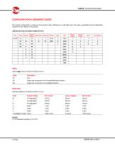
The ordering configuration is made up of the product name, followed by a multi digit code. The code is generated by the configuration required for each aspect of the joystick. NY Single axis movement in the Forward/Backward direction XN Single axis movement in the Left/Right direction Supply Voltage NOTES (1) 5V Regulated equates to 4.5-5.5V.
Open the catalog to page 3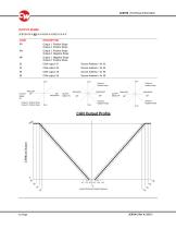
OUTPUT SENSE CODE DESCRIPTION PP Output 1: Positive Slope Output 2: Positive Slope PN Output 1: Positive Slope Output 2: Negative Slope NP Output 1: Negative Slope Output 2: Positive Slope 33 CAN output: 51 Source Address = 0x 33 34 CAN output: 52 Source Address = 0x 34 35 CAN output: 53 Source Address = 0x 35 PAN Qutput Prpfile 4 | Page JC8100 | Rev A | 03/23
Open the catalog to page 4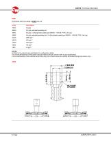
Code Description NHA0 No grip, extended operating rod NHFL No grip, 13x flying leads (cable type 30AWG - 19/0.06, PTFE, Uni-Lay) NHAF No grip, extended operating rod, 13x flying leads (cable type 30AWG - 19/0.06, PTFE, Uni-Lay) (1) Refer to the relevant grip specification for configuration details. The overall performance of the joystick may be limited by the grip chosen (refer to grip specification). It is the responsibility of the customer when fitting the grip to ensure wires are correctly terminated (flying lead version only).
Open the catalog to page 6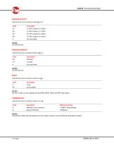
(3) The ‘N' option is only available with the NH00, NHAF, NHA0 and NHFL grip options Mating Connector Code Description A AMPseal 23-way connector The joystick is fitted with gold plated pins so the mating connector must be fitted with gold plated contacts
Open the catalog to page 11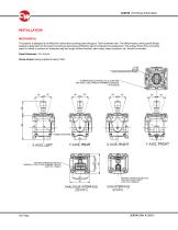
The joystick is designed to be fitted from below the mounting panel through a 72mm diameter hole. The effectiveness of the joystick flange sealing is dependent on the panel mounting surface being sufficiently rigid to compress the sealing boot. The surface finish of the mounting panel is critical to achieve an adequate seal and rough surface finishes, paint chips, deep scratches, etc. should be avoided. Screw torque (using supplied screws): 5Nm HOLE IN MOUNTING PANEL 6.1 MM HOLES IN PANEL TO ALLOW THE M6 TORX (T30) THREAD FORMING SCREWS REAR X AXIS. RIGHT Y AXIS FRONT
Open the catalog to page 12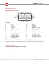
ELECTRICAL CONNECTIONS 23-Way Analogue Joystick Connector See chosen grip specification See chosen grip specification See chosen grip specification See chosen grip specification See chosen grip specification See chosen grip specification See chosen grip specification See chosen grip specification See chosen grip specification See chosen grip specification See chosen grip specification See chosen grip specification See chosen grip specification Do not Connect – Curtiss-Wright programming pin NOTES The joystick is fitted with gold plated pins so the mating connector must be fitted with gold plated...
Open the catalog to page 13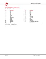
Analogue Joystick Base-to-Grip Connections 23-way AMPseal to flying leads Pin Cable type 30AWG - 19/0.06, PTFE, Uni-Lay 23 Do not Connect - Curtiss-Wright programming pin n/a
Open the catalog to page 14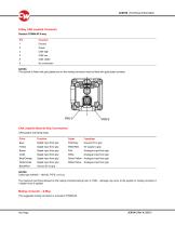
The joystick is fitted with gold plated pins so the mating connector must be fitted with gold plated contacts CAN Joystick Base-to-Grip Connections CAN joystick with flying leads. Digital input from grip Digital input from grip Digital input from grip Digital input from grip Digital input from grip Digital input from grip Ground 0V to grip Function Ground 0V to grip 5V supply to grip Analogue input from grip Analogue input from grip Analogue input from grip Analogue input from grip Cable type 30AWG - 19/0.06, PTFE, Uni-Lay The maximum pull force allowed on the mating connector/wiring loom is...
Open the catalog to page 15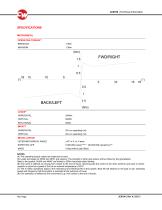
SPECIFICATIONS MECHANICAL OPERATING TORQUE(4) BREAKOUT IMPACT HORIZONTAL MISCELLANOUS LEVER MECHANICAL ANGLE EXPECTED LIFE 0.9kg (without grip fitted) NOTES (4) The operating torque values are measured on-axis. (5) Loads are based on NH00 and NHFL grip options. The strength of other grip options will be limited by the grip/adaptor fitted to the joystick. NHA0 and NHAF are limited to 25Nm horizontal static loading (6) One cycle is defined as moving from center to the end of travel, returning past the center to the other extreme and back to center. Joystick is cycled at a speed of 2Hz at an ambient...
Open the catalog to page 16All CURTISS-WRIGHT INDUSTRIAL DIVISION catalogs and technical brochures
 WM-H10
6 Pages
 WM-830
7 Pages
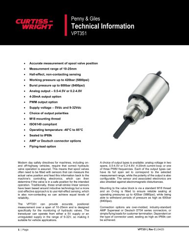 VPT351
11 Pages
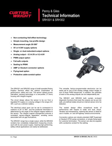 SRH301 & SRH302
11 Pages
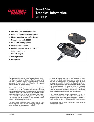 NRH300DP
11 Pages
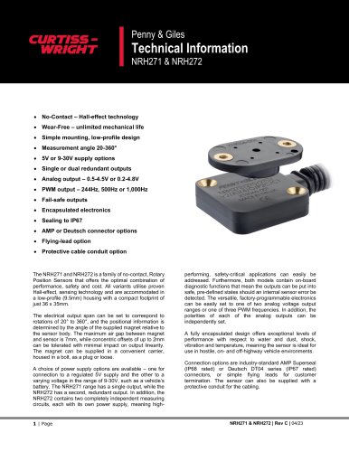 NRH271 & NRH272
13 Pages
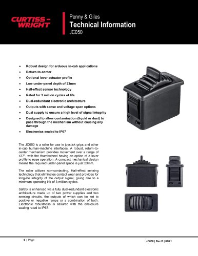 JC050
JC05011 Pages
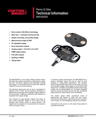 NRH305DR
11 Pages
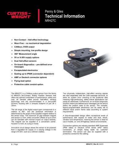 NRH27C
11 Pages
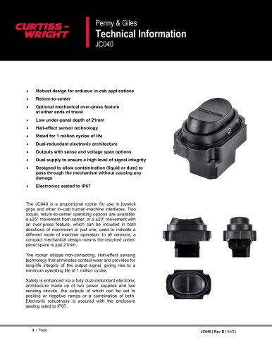 JC040
JC04010 Pages
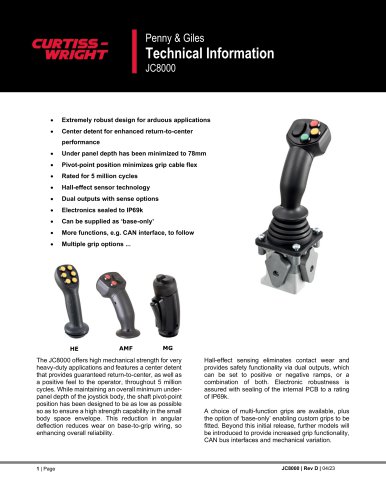 JC8000
15 Pages
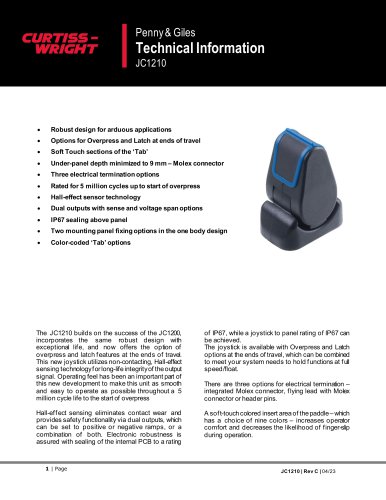 JC1210
20 Pages
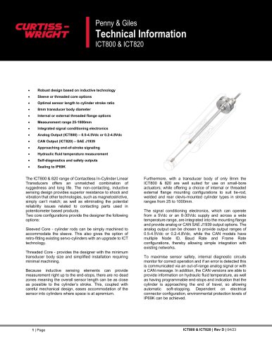 ICT800 & ICT820
19 Pages
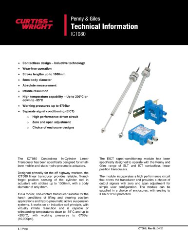 ICT080
15 Pages
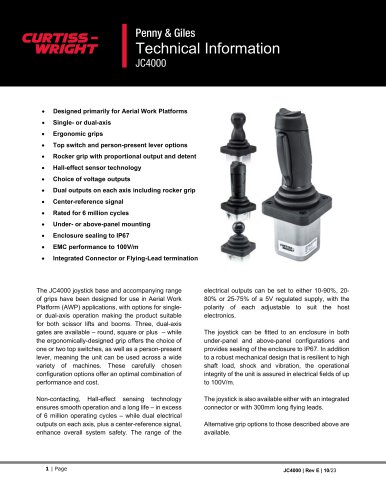 JC4000
23 Pages
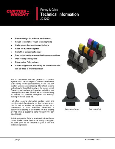 JC1200
12 Pages
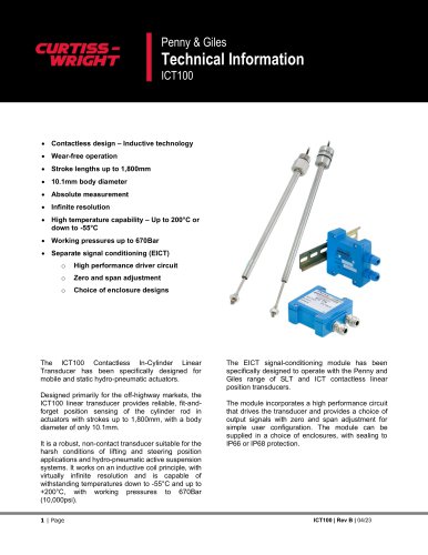 ICT100
15 Pages
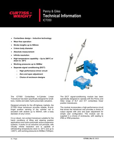 ICT050
17 Pages
 Rotary Position Sensors
6 Pages
 CWTI
CWTI4 Pages
 Industrial Division
4 Pages

- Actuator
- Electric actuator
- Single-pole switch
- Position transducer
- Tilt sensor
- HMI
- Control pedal
- Single pedal pedal
- Panel-mount HMI
- Electronic pedal
- Digital inclination sensor
- Rocker switch
- 2-axis tilt sensor
- No-contact position sensor
- Analog inclination sensor
- IP67 inclination sensor
- Compact position sensor
- Angular position sensor
- Single-axis joystick
- Compact switch