


- Products
- Catalogs
- News & Trends
- Exhibitions
JC4000
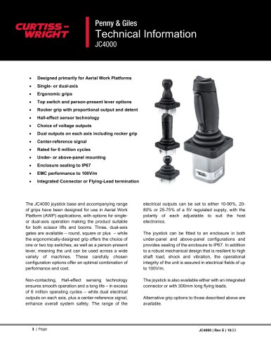
JC4000
- Utilizes Hall-effect sensing technology for smooth operation and durability, exceeding 6 million cycles.
- Includes dual electrical outputs per axis and a center-reference signal for enhanced safety.
- Output ranges are adjustable, with mounting options and IP67 sealing.
- Robust design withstands high loads, shock, and vibration, with EMC performance up to 100V/m.
- Available with integrated connector or flying leads.
- Electrical: Supply voltage is 5Vdc ± 0.5Vdc, with detailed accuracy specifications.
- Grip Switches: Contact rating, resistance, and mechanical life are specified.
- HJ Grip Functions: Describes output sense options and detent features.
Catalog excerpts
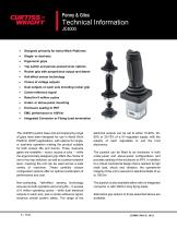
Penny & Giles Technical InformationJC4000 • Designed primarily for Aerial Work Platforms • Ergonomic grips • Top switch and person-present lever options • Rocker grip with proportional output and detent • Hall-effect sensor technology • Choice of voltage outputs • Dual outputs on each axis including rocker grip • Center-reference signal • Rated for 6 million cycles • Under- or above-panel mounting • Integrated Connector or Flying-Lead termination The JC4000 joystick base and accompanying range of grips have been designed for use in Aerial Work Platform (AWP) applications, with options for single-or dual-axis operation making the product suitable for both scissor lifts and booms. Three, dual-axis gates are available - round, square or plus - while the ergonomically-designed grip offers the choice of one or two top switches, as well as a person-present lever, meaning the unit can be used across a wide variety of machines. These carefully chosen configuration options offer an optimal combination of performance and cost. Non-contacting, Hall-effect sensing technology ensures smooth operation and a long life - in excess of 6 million operating cycles - while dual electrical outputs on each axis, plus a center-reference signal, enhance overall system safety. The range of the electrical outputs can be set to either 10-90%, 2080% or 25-75% of a 5V regulated supply, with the polarity of each adjustable to suit the host electronics. The joystick can be fitted to an enclosure in both under-panel and above-panel configurations and provides sealing of the enclosure to IP67. In addition to a robust mechanical design that is resilient to high shaft load, shock and vibration, the operational integrity of the unit is assured in electrical fields of up to 100V/m. The joystick is also available either with an integrated connector or with 300mm long flying leads. Alternative grip options to those described above are available.
Open the catalog to page 1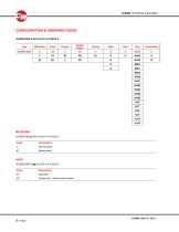
Code Description Code Description NY Single axis - forward and reverse
Open the catalog to page 3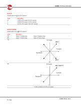
PN Output 1: Positive slope Output 2: Negative slope PP Output 1: Positive slope Output 2: Positive slope
Open the catalog to page 4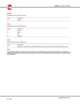
Code Description Code Description Code Description A Fitted with a biased seat to provide additional force when the operator moves the joystick towards the corners The biased seat is fitted to all joysticks, but its function can only be felt in Square and Round gate joysticks. The biased seat enables the operating rod to move more easily along the X and Y axes of the joystick, but it does not prevent movement into the corner positions.
Open the catalog to page 5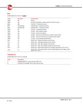
Grip Type Grip Function No grip, Flying leads to enable customer to fit their own grip Plain ball – no electrical functions Extended Ball Extended ball - no electrical functions Extended Ball Extended ball - no electrical functions Full grip – no electrical functions Full grip – with a single top switch Full grip – with two top switches Full grip – with two top switches and an operator present switch Full grip – with one top switch and an operator present switch Full grip – with an operator present switch Rocker Grip – Without overpress at ends of travel Rocker Grip – With Right overpress at...
Open the catalog to page 6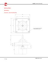
INSTALLATION MECHANICAL Dimensions – Above Panel Mounting
Open the catalog to page 7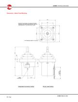
JC4000 | Technical Information Dimensions - Below Panel Mounting STAND OFF FEATURES 4 PLACES PROTRUDE THROUGH THE GA TER AND CONTROL THE SEAL COMPRESSION AT THE MOUNTING FLANGE M4 THREADED INSERT 4 PLACES Integrated Connector Option Flying Lead Option 8 | Page JC4000 | Rev E | 10/23
Open the catalog to page 8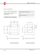
Panel Cut-out and fixing details PANEL CUT-OUT DETAILS – BELOW-PANEL MOUNT 64.5 mm square profile with 7.5mm maximum radius in each corner and 4 additional holes for the mounting screws PANEL CUT-OUT DETAILS – ABOVE-PANEL MOUNT 60 mm diameter hole with 4 additional holes for the mounting screws RECOMMENDED PANEL THICKNESS FIXING HARDWARE M4 screws – it is recommended that self-locking nuts are used when using the above panel mounting The below panel mounting has integrated M4 x 0.7 Brass inserts RECOMMENDED SCREW TIGHTENING TORQUE TO ACHIEVE OPTIMUM PANEL SEAL PERFORMANCE Above Panel Mounting...
Open the catalog to page 9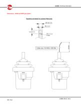
Dimensions – NH00 and NHF0 grip option Operating rod details for customer fitted grips
Open the catalog to page 10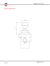
Dimensions – B000 grip option
Open the catalog to page 11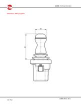
Dimensions – B001 grip option
Open the catalog to page 12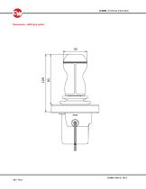
Dimensions – B002 grip option
Open the catalog to page 13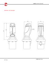
Dimensions – HG** grip option
Open the catalog to page 14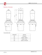
Ordering Code
Open the catalog to page 15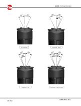
Overpress - Left Overpress - Right Overpress – Left and Right
Open the catalog to page 16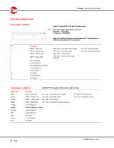
Molex 12-way 53047-1210 with Tin-plated pinsNote: the mating connector must be fitted with Tin-plated pins to ensure stable output from the joystick Pin Function = Top switch left or single HJ** grip = Primary Output = Top switch right HJ** grip = Secondary Output = Lever switch = Common for all grip Not connected Y-axis Output 2 Center Reference Voltage X-axis Output 2 X-axis Output 1 0V supply Y-axis Output 1 5V supply NHF0 = Blue wire NHF0 = Green wire NHF0 = Yellow Wire HG** grip HG** grip HG** grip Termination: CODE B 22 AWG PTFE insulated 19/0.15 wires, 300 mm longWire Color Function HG**...
Open the catalog to page 17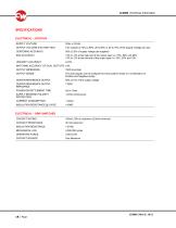
SPECIFICATIONS ELECTRICAL - JOYSTICK SUPPLY VOLTAGE OUTPUT VOLTAGE (FACTORY SET) Two outputs of 10% to 90%, 20 to 80% or 25 to 75% of the Supply Voltage per axis CENTERING ACCURACY 50% ±2.5% of supply voltage (as supplied) +2% to -3% at the high end of the output span i.e. 75%, 80% and 90% +3% to -2% at the low end of the output span i.e. 25%. 20% and 10% LINEARITY ACCURACY MATCHING ACCURACY OF DUAL OUTPUTS ±4% OUTPUT IMPEDANCE OUTPUT SENSE The dual outputs can be configured to have positive ramps or a combination of Positive and Negative ramps CENTER REFERENCE OUTPUT CENTER REFERENCE OUTPUT...
Open the catalog to page 18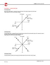
ELECTRICAL – HJ GRIP FUNCTIONS HJ*A Output Sense Both output ramps positive – Actuate the rocker to the left for 0.5V output and right for the 4.5V output Output range 0.5 to 4.5V is the only option available HJ*B Output Sense Crossed output ramps – Actuate the rocker to the left for Primary Output 0.5V and Secondary output 4.5V. Actuate the rocker to the right for Primary output 0.5V and secondary output 0.5V Output range 0.5 to 4.5V is the only option available HJ*B Output at detent If the detent feature is fitted, then the output at the detent position will be 18%/ 82% of the 5V supply
Open the catalog to page 19All CURTISS-WRIGHT INDUSTRIAL DIVISION catalogs and technical brochures
 WM-H10
6 Pages
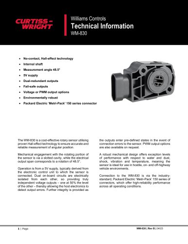 WM-830
7 Pages
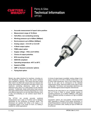 VPT351
11 Pages
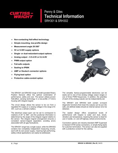 SRH301 & SRH302
11 Pages
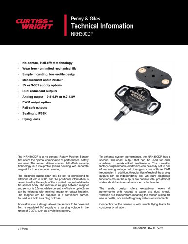 NRH300DP
11 Pages
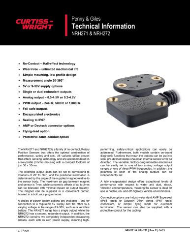 NRH271 & NRH272
13 Pages
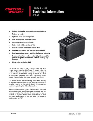 JC050
JC05011 Pages
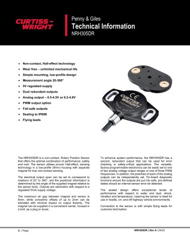 NRH305DR
11 Pages
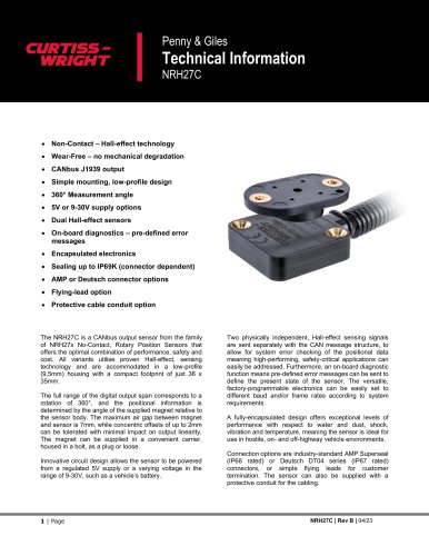 NRH27C
11 Pages
 JC8100
19 Pages
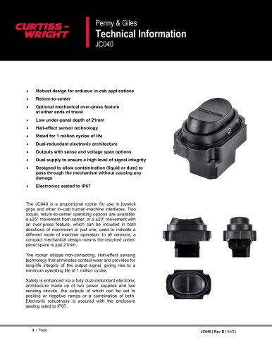 JC040
JC04010 Pages
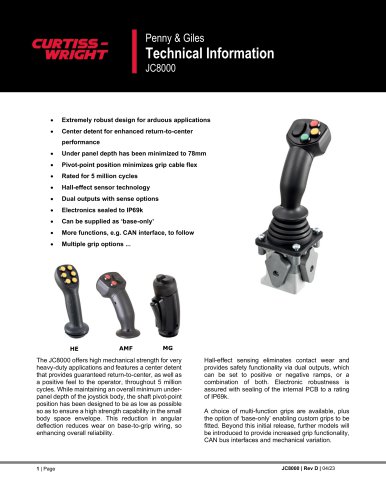 JC8000
15 Pages
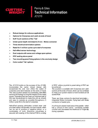 JC1210
20 Pages
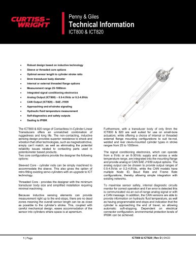 ICT800 & ICT820
19 Pages
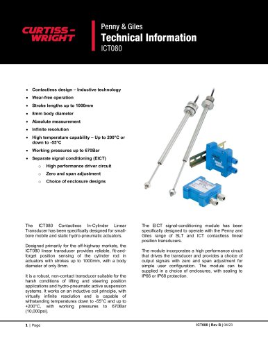 ICT080
15 Pages
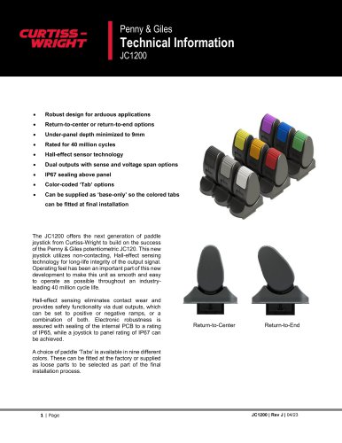 JC1200
12 Pages
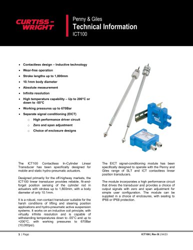 ICT100
15 Pages
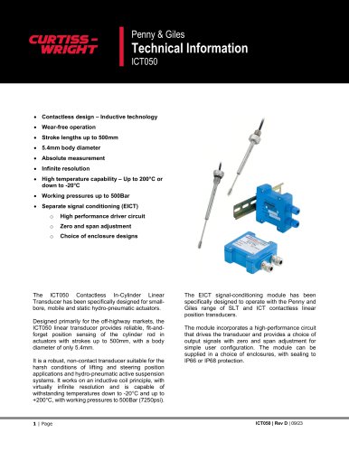 ICT050
17 Pages
 Rotary Position Sensors
6 Pages
 CWTI
CWTI4 Pages
 Industrial Division
4 Pages

- Actuator
- Electric actuator
- Single-pole switch
- Position transducer
- Tilt sensor
- HMI
- Control pedal
- Single pedal pedal
- Panel-mount HMI
- Electronic pedal
- Digital inclination sensor
- Rocker switch
- 2-axis tilt sensor
- No-contact position sensor
- Analog inclination sensor
- IP67 inclination sensor
- Compact position sensor
- Angular position sensor
- Single-axis joystick
- Compact switch