


- Products
- Catalogs
- News & Trends
- Exhibitions
JC1210
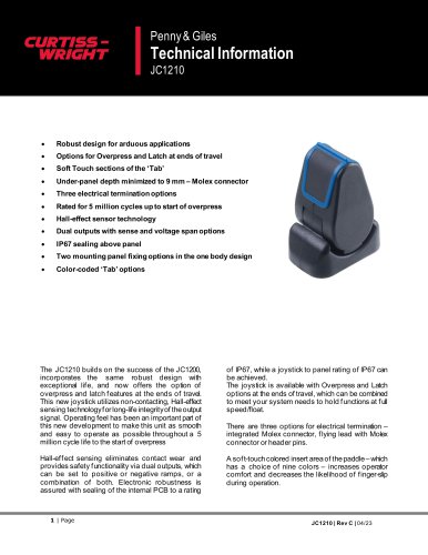
JC1210
- Non-contacting Hall-effect sensing minimizes wear and provides dual output safety functionality.
- IP67 sealing ensures protection for both the internal PCB and the joystick-to-panel interface.
- Options for overpress and latch at travel ends allow functions to be maintained at full speed or float.
- Three electrical termination options: integrated Molex connector, flying lead with Molex connector, or header pins.
- Soft-touch paddle inserts available in nine colors to enhance operator comfort.
- Electrical: Operates on a 5Vdc supply voltage, with a current of ≤ 25mA, over-voltage protection up to 10Vdc, and dual analogue ratiometric output.
- Mechanical: Operative force ranges from 1.0N to 8N depending on features, with a mechanical angle of ±30° or ±40° with overpress/latch.
- Environmental: Operating temperature ranges from -40°C to 85°C, with IP67 protection and compliance with various IEC and ISO standards for durability and resistance.
- Offers multiple mounting options with specific screw recommendations for secure installation.
- Details electrical connections for each termination option, emphasizing the use of gold-plated pins for stable output.
Catalog excerpts
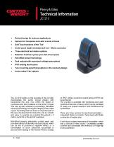
Penny & Giles • Robust design for arduous applications • Options for Overpress and Latch at ends of travel • Soft Touch sections of the ‘Tab’ • Under-panel depth minimized to 9 mm - Molex connector • Three electrical termination options • Rated for 5 million cycles up to start of overpress • Hall-effect sensor technology • Dual outputs with sense and voltage span options • IP67 sealing above panel • Two mounting panel fixing options in the one body design The JC1210 builds on the success of the JC1200, incorporates the same robust design with exceptional life, and now offers the option of overpress and latch features at the ends of travel. This new joystick utilizes non-contacting, Hall-effect sensing technology for long-life integrity of the output signal. Operating feel has been an important part of this new development to make this unit as smooth and easy to operate as possible throughout a 5 million cycle life to the start of overpress Hall-effect sensing eliminates contact wear and provides safety functionality via dual outputs, which can be set to positive or negative ramps, or a combination of both. Electronic robustness is assured with sealing of the internal PCB to a rating of IP67, while a joystick to panel rating of IP67 can be achieved. The joystick is available with Overpress and Latch options at the ends of travel, which can be combined to meet your system needs to hold functions at full speed/float. There are three options for electrical termination -integrated Molex connector, flying lead with Molex connector or header pins. A soft-touch colored insert area of the paddle - which has a choice of nine colors - increases operator comfort and decreases the likelihood of finger-slip during operation.
Open the catalog to page 1
© 2023 Curtiss-Wright. All rights reserved. Curtiss-Wright accepts no responsibility for possible errors in catalogs, brochures and other printed material. Curtiss-Wright reserves the right to alter its products without prior notice. This also applies to products already ordered provided that such alterations can be made without affecting agreed specifications. All trademarks in this material are properties of their respective owners.
Open the catalog to page 2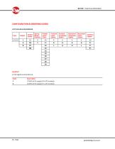
Code Description
Open the catalog to page 3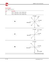
OUTPUT SENSE JC1210-X-XX-X-XX-XXXX-XX Code Output 1: Positive slope Output 2: Negative slope Output 1: Positive slope Output 2: Positive slope Output 1: Negative slope Output 2: Negative slope
Open the catalog to page 4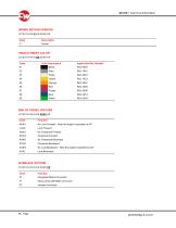
Code Description Color Description Black Grey White Yellow Orange Red Purple Code Function NXXX No Lock Forward - Note the angle of operation is 30° LXXX Lock Forward XNXX No Overpress Forward XOXX Overpress Forward XXNX No O verpress B ackward XXOX Overpress Backward XXXN No Lock Backward - Note the angle of operation is 30° XXXL Lock Backward Code Function C1 Integrated Molex Connector F1 Flying Lead with Molex connector
Open the catalog to page 5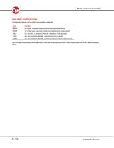
AVAILABLE CONFIGURATIONS The following feature configurations are available as standard: Code Function NNNN No lock or overpress forward; no lock or overpress backward NOON No lock forward; overpress forward and backward; no lock backward LNNL Lock forward, no overpress forward or backward; lock backward LOOL Lock and overpress forward; overpress and lock backward LOON Lock and overpress forward; overpress backward but no lock backward Other feature configurations will be available in the future and please refer to the Curtiss Wright sales team for the latest availability status:
Open the catalog to page 6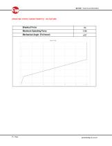
OPERATING FORCE CHARACTERISTICS – NO FEATURE
Open the catalog to page 7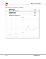
OPERATING FORCE CHARACTERISTICS - OVERPRESS Breakout Force Maximum Operating Force Overpress Force Overpress Angle Mechanical Angle (Full travel)
Open the catalog to page 8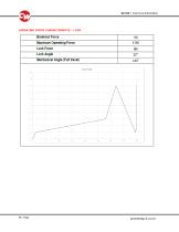
OPERATING FORCE CHARACTERISTICS - LOCK Breakout Force Maximum Operating Force Lock Force Lock Angle Mechanical Angle (Full travel) F-cree Hrahla
Open the catalog to page 9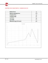
OPERATING FORCE CHARACTERISTICS - OVERPRESS AND LOCK Breakout Force Maximum Operating Force Overpress Force Overpress Angle Lock Force Lock Angle Mechanical Angle (Full travel)
Open the catalog to page 10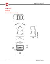
INSTALLATION MECHANICAL Dimensions – Molex Connector – C1
Open the catalog to page 11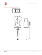
Dimensions - Flying lead with Molex connector – F1
Open the catalog to page 12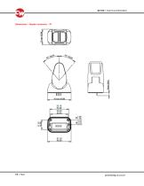
Dimensions - Header connector – P1
Open the catalog to page 13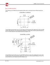
Panel cut-out/Mounting Details The f ollowing cut-out details show the largest hole that can be cut and still have an effective seal to the panel. 2 screw f itting - on centre line Curtiss-Wright recommend the use of 2 x EJOT WN1451-K30-8 screws when utilising the 2 screw mounting points on the centre line. The screws should be tightened to 0.55Nm with a minimum panel thickness of 3 mm. For thicker panels the screw length should be increased to suit. 4 screw f itting – in corners Curtiss-Wright recommend the use of 4 x EJOT WN1451-K25-12 screws when utilising the 4 corner screw mounting points....
Open the catalog to page 14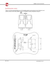
Panel Mounting Details - standard There is a minimal spacing between two JC1210 paddle joysticks to ensure there isn’t any influence on one paddle’s output from the other paddles magnet. In a standard mounting configuration the gap is:
Open the catalog to page 15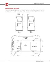
Panel Mounting Details - Non-Standard There is a minimal spacing between two JC1210 paddle joysticks to ensure there isn’t any influence on one paddle’s output from the other paddles magnet. In a non-standard mounting configuration where one of the paddles has been mounted in the opposite direction the gap is:
Open the catalog to page 16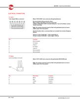
ELECTRICAL CONNECTIONS C1 option 7-pin integral Molex connector Molex 70553-0006 7-pin connector with gold-plated pins Recommended mating connector either: Molex 70400 14-56-2074 (connector and pin kit) or Molex 70066 50-57-9407 connector body plus 7 pins to the Molex number 70058 16-02-0082. Note: the mating connector must be fitted with gold-plated pins to ensure stable output from the joystick Standard Cables with a connector fitted are available from Curtiss Wright as follows: CW part number SA301649 – cable length 500 mm CW part number SA308599 – cable length 1,000 mm F1 Option 4-pin in-line...
Open the catalog to page 17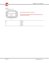
P1 option 4-pin in-line Molex connector 4-way gold plated header pins at 2.54 mm pitch Note: the mating connector must be fitted with gold-plated pins to ensure stable output from the joystick
Open the catalog to page 18All CURTISS-WRIGHT INDUSTRIAL DIVISION catalogs and technical brochures
 WM-H10
6 Pages
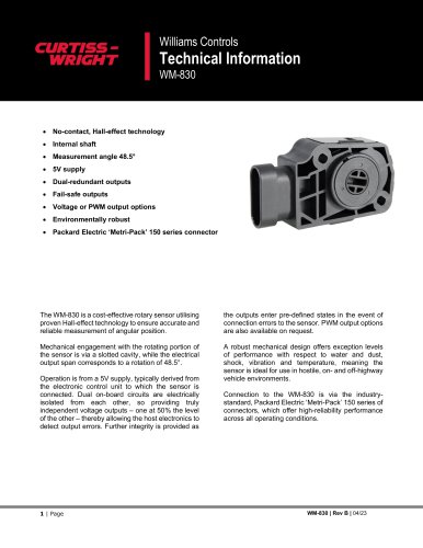 WM-830
7 Pages
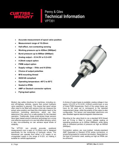 VPT351
11 Pages
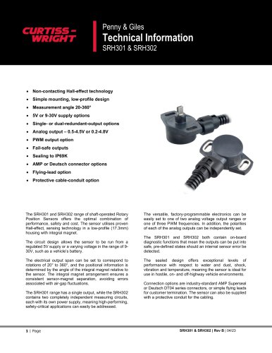 SRH301 & SRH302
11 Pages
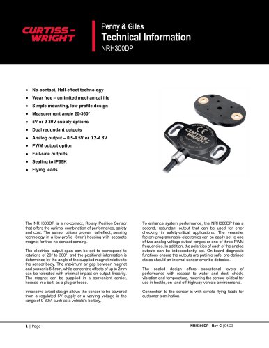 NRH300DP
11 Pages
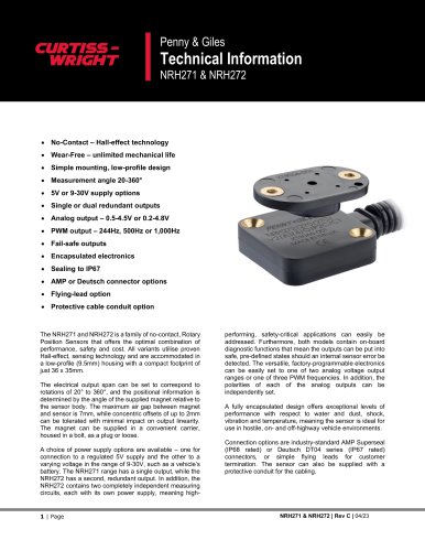 NRH271 & NRH272
13 Pages
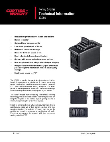 JC050
JC05011 Pages
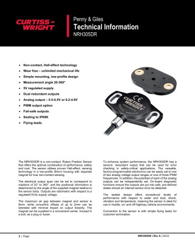 NRH305DR
11 Pages
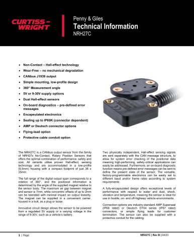 NRH27C
11 Pages
 JC8100
19 Pages
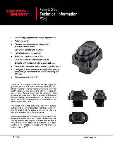 JC040
JC04010 Pages
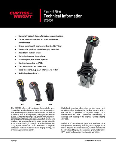 JC8000
15 Pages
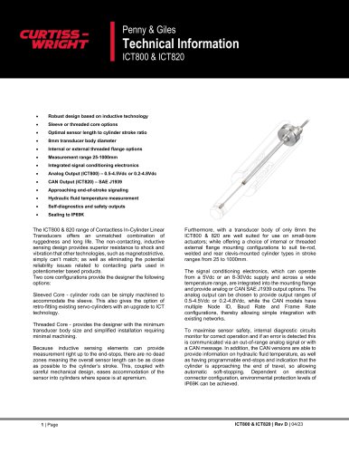 ICT800 & ICT820
19 Pages
 ICT080
15 Pages
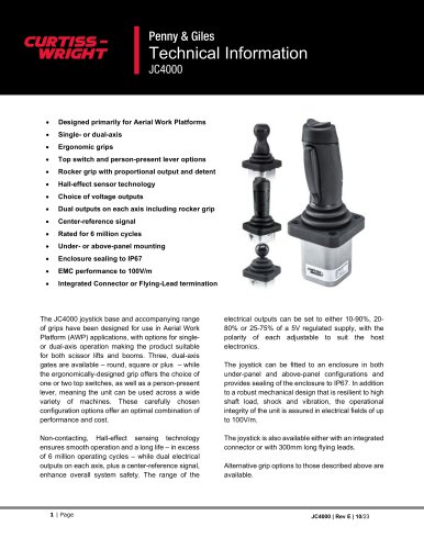 JC4000
23 Pages
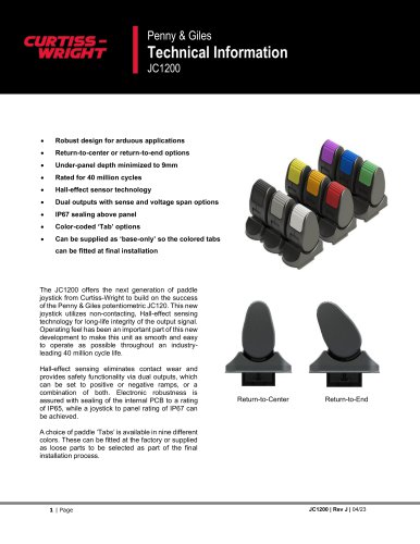 JC1200
12 Pages
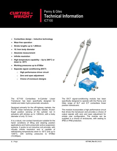 ICT100
15 Pages
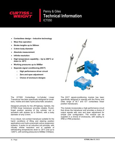 ICT050
17 Pages
 Rotary Position Sensors
6 Pages
 CWTI
CWTI4 Pages
 Industrial Division
4 Pages

- Actuator
- Electric actuator
- Single-pole switch
- Position transducer
- Tilt sensor
- HMI
- Control pedal
- Single pedal pedal
- Panel-mount HMI
- Electronic pedal
- Digital inclination sensor
- Rocker switch
- 2-axis tilt sensor
- No-contact position sensor
- Analog inclination sensor
- IP67 inclination sensor
- Compact position sensor
- Angular position sensor
- Single-axis joystick
- Compact switch