
- Catalogs
- CURTISS-WRIGHT INDUSTRIAL DIVISION
- ICT800 & ICT820


- Products
- Catalogs
- News & Trends
- Exhibitions
ICT800 & ICT820
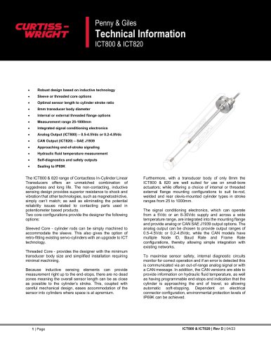
ICT800 & ICT820
- Sleeved Core: Facilitates easy retrofitting of existing servo-cylinders.
- Threaded Core: Reduces transducer body size and simplifies installation.
- Measurement extends to end-stops, eliminating dead zones.
- Compact 8mm transducer body suitable for small-bore actuators.
- Available in internal or threaded external flange mounting configurations.
- Stroke ranges from 25 to 1000mm.
- Electrical: Includes supply voltage options, current consumption, and protection features. Output ranges and linearity specifications are detailed.
- Environmental: Designed for robust performance in various conditions.
Catalog excerpts
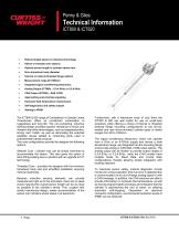
Penny & Giles • Robust design based on inductive technology • Sleeve or threaded core options • Optimal sensor length to cylinder stroke ratio • 8mm transducer body diameter • Internal or external threaded flange options • Integrated signal conditioning electronics • Approaching end-of-stroke signaling • Hydraulic fluid temperature measurement • Self-diagnostics and safety outputs The ICT800 & 820 range of Contactless In-Cylinder Linear Transducers offers an unmatched combination of ruggedness and long life. The non-contacting, inductive sensing design provides superior resistance to shock and vibration that other technologies, such as magnetostrictive, simply can't match; as well as eliminating the potential reliability issues related to contacting parts used in potentiometer based products. Two core configurations provide the designer the following options: Sleeved Core - cylinder rods can be simply machined to accommodate the sleeve. This also gives the option of retro-fitting existing servo-cylinders with an upgrade to ICT technology. Threaded Core - provides the designer with the minimum transducer body size and simplified installation requiring minimal machining. Because inductive sensing elements can provide measurement right up to the end-stops, there are no dead zones meaning the overall sensor length can be as close as possible to the cylinder's stroke. This, coupled with careful mechanical design, eases accommodation of the sensor into cylinders where space is at apremium. Furthermore, with a transducer body of only 8mm the ICT800 & 820 are well suited for use on small-bore actuators; while offering a choice of internal or threaded external flange mounting configurations to suit tie-rod, welded and rear clevis-mounted cylinder types in stroke ranges from 25 to 1000mm. The signal conditioning electronics, which can operate from a 5Vdc or an 8-30Vdc supply and across a wide temperature range, are integrated into the mounting flange and provide analog or CAN SAE J1939 output options. The analog output can be chosen to provide output ranges of 0.5-4.5Vdc or 0.2-4.8Vdc, while the CAN models have multiple Node ID, Baud Rate and Frame Rate configurations, thereby allowing simple integration with existing networks. To maximise sensor safety, internal diagnostic circuits monitor for correct operation and if an error is detected this is communicated via an out-of-range analog signal or with a CAN message. In addition, the CAN versions are able to provide information on hydraulic fluid temperature, as well as having programmable end-stops and indication that the cylinder is approaching the end of travel, so allowing automatic soft-stopping. Dependent on electrical connector configuration, environmental protection levels of IP69K can be achieved.
Open the catalog to page 1
© 2023 Curtiss-Wright. All rights reserved. Curtiss-Wright accepts no responsibility for possible errors in catalogs, brochures and other printed material. Curtiss-Wright reserves the right to alter its products without prior notice. This also applies to products already ordered provided that such alterations can be made without affecting agreed specifications. All trademarks in this material are properties of their respective owners. 3 | Page
Open the catalog to page 3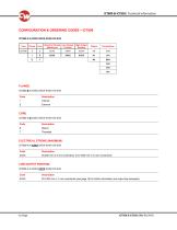
Code Description Code Description XXXX 25-200 mm in 5 mm increments, 210-1000 mm in 10 mm increments Code Description XXXX 25-1000 mm in 1 mm increments (see page 15 for further information and output law examples)
Open the catalog to page 4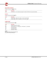
XXXX 25-1000 mm in 1 mm increments (see page 15 for further information and output law examples) A1 Analog voltage: 10-90% of 5V supply or 0.5-4.5V of 9-32V supply A5 Analog voltage: 4-96% of 5V supply or 0.2-4.8V of 9-32V supply C01 Flange mounted M12 connector BXX Cable with gland, XX = cable length - 01-06 metres in 1 m increments C01 and BXX options with external flange only. FPX options with internal flange only.
Open the catalog to page 5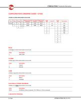
Code Description XXXX 25-200mm in 5mm increments, 210-1000mm in 10mm increments
Open the catalog to page 6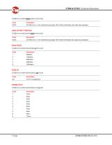
XXXX 25-1000 mm in 1 mm increments (see page 16 for further information and output law examples) XXXX 25-1000 mm in 1 mm increments (see page 16 for further information and output law examples)
Open the catalog to page 7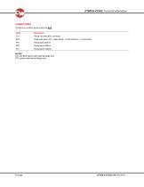
C01 Flange mounted M12 connector BXX Cable with gland, XX = cable length - 01-06 metres in 1 m increments C01 and BXX options with external flange only. FPX options with internal flange only.
Open the catalog to page 8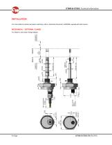
INSTALLATION For more detail of cylinder and piston machining, refer to Instruction Document, AI209399, supplied with each sensor. MECHANICAL – EXTERNAL FLANGE For Detail A, see section Flange Details.
Open the catalog to page 9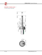
MECHANICAL – INTERNAL FLANGE For Detail B, see section Flange Details.
Open the catalog to page 10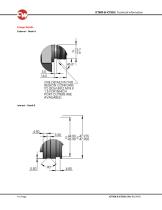
Flange Details External - Detail A REGION CONFORM TO IS06149/2 M18 X 1.5 FOR WHICH PORT CUTTERS ARE AVAILABLE)
Open the catalog to page 11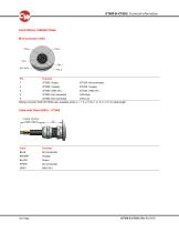
Mating connector SA210517/MKx also available where x = 1, 5 or 10 for 1 m, 5 m, or 10 m cable length Color Function BROWN Vsupply BLACK Output
Open the catalog to page 12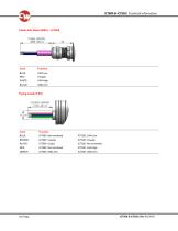
Color Function BLUE CAN Low Color Function BLUE ICT800: Not connected ICT820: CAN Low ICT820: Vsupply ICT820: Not connected ICT820: CAN High ICT820: GND (0V)
Open the catalog to page 13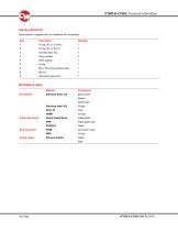
Each sensor is supplied with an Installation Kit comprising: Description Quantity MATERIALS USED Cable with Gland M12 Connector Flying Leads Nickel Plated Brass FPM Silicone Rubber Body (case) Guide tube Cable gland Cable gland seal Connector insert
Open the catalog to page 14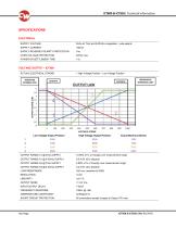
SPECIFICATIONS ELECTRICAL SUPPLY VOLTAGE SUPPLY CURRENT SUPPLY REVERSE POLARITY PROTECTION OVER-VOLTAGE PROTECTION POWER-ON SETTLEMENT TIME VOLTAGE OUTPUT – ICT800 ACTUAL ELECTRICAL STROKE Low Voltage Output Position = High Voltage Position – Low Voltage Position High Voltage Output Position Actual Electrical Stroke OUTPUT RANGE A1 @ 5Vdc SUPPLY 10-90% ±1% of Vsupply over measurement range OUTPUT RANGE A1 @ 8-30Vdc SUPPLY OUTPUT RANGE A5 @ 5Vdc SUPPLY 4-96% ±1% of Vsupply over measurement range OUTPUT RANGE A5 @ 8-30Vdc SUPPLY LOAD RESISTANCE OUTPUT NOISE INPUT/OUTPUT DELAY FREQUENCY RESPONSE...
Open the catalog to page 15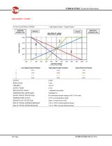
Low Signal Output Position OUTPUT NOISE INPUT/OUTPUT DELAY TEMPERATURE COEFFICIENT SHORT-CIRCUIT PROTECTION TEMPERATURE OUTPUT SENSOR FAULT DETECTION END OF TRAVEL WARNING MESSAGE END OF TRAVEL ERROR MESSAGE High Signal Output Position Actual Electrical Stroke 0000 1000 = selected Frame Rate <±300ppm/°C All connections except Vsupply to NC 10 Vdc max. <±3°C over temperature range Open- or short-circuit of coil <3% or >97% of actual electrical stroke <1 % or >99% of actual electrical stroke
Open the catalog to page 16All CURTISS-WRIGHT INDUSTRIAL DIVISION catalogs and technical brochures
 WM-H10
6 Pages
 WM-830
7 Pages
 VPT351
11 Pages
 SRH301 & SRH302
11 Pages
 NRH300DP
11 Pages
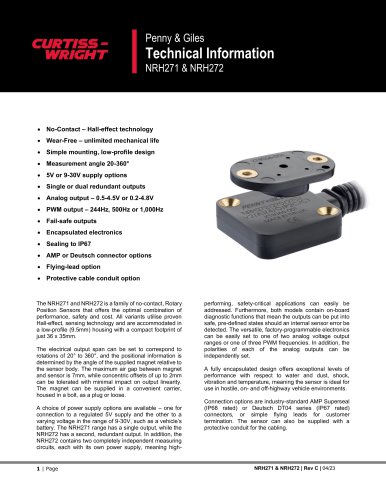 NRH271 & NRH272
13 Pages
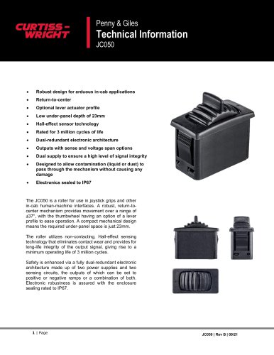 JC050
JC05011 Pages
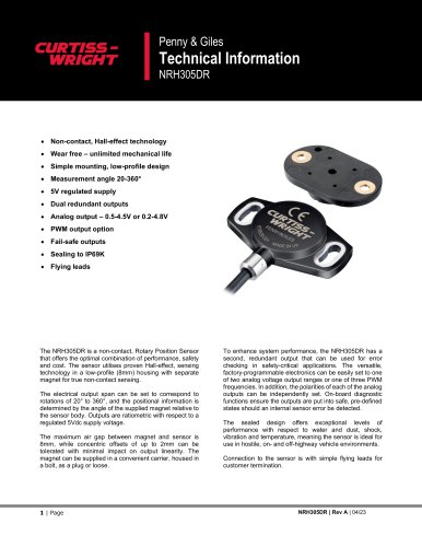 NRH305DR
11 Pages
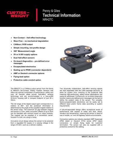 NRH27C
11 Pages
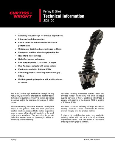 JC8100
19 Pages
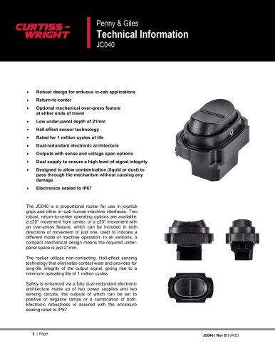 JC040
JC04010 Pages
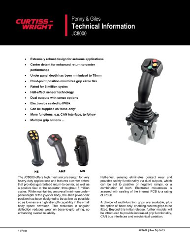 JC8000
15 Pages
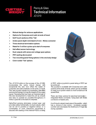 JC1210
20 Pages
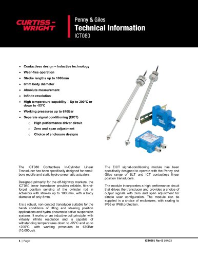 ICT080
15 Pages
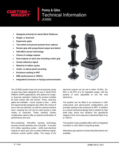 JC4000
23 Pages
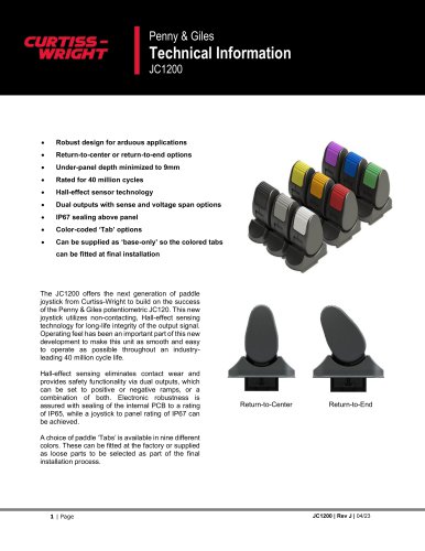 JC1200
12 Pages
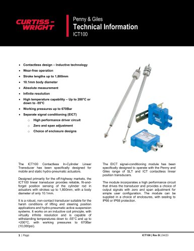 ICT100
15 Pages
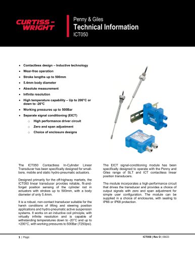 ICT050
17 Pages
 Rotary Position Sensors
6 Pages
 CWTI
CWTI4 Pages
 Industrial Division
4 Pages

- Electric actuator
- Single-pole switch
- Position transducer
- Tilt sensor
- HMI
- Control pedal
- Single pedal pedal
- Panel-mount HMI
- Electronic pedal
- Digital inclination sensor
- Rocker switch
- 2-axis tilt sensor
- No-contact position sensor
- Analog inclination sensor
- IP67 inclination sensor
- Compact position sensor
- Angular position sensor
- Single-axis joystick
- Compact switch