


- Products
- Catalogs
- News & Trends
- Exhibitions
ICT050
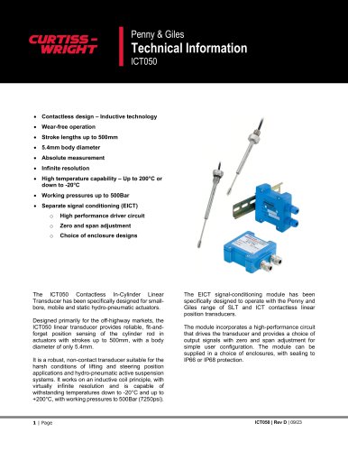
ICT050
Electrical: Measurement range up to 500mm, infinite sensor resolution, and various supply voltage options depending on the card fitted. Outputs include standard and extended voltage, current, and PWM options.
Mechanical: Maximum sensor working pressure is 500Bar, with specific torque requirements for mounting and lid screws.
Environmental: Operating and storage temperature ranges are specified for both the sensor and EICT/EICTM. Sealing standards are IP66 for EICT and IP68 for EICTM.
Catalog excerpts
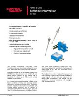
Penny & Giles • Contactless design - Inductive technology • Wear-free operation • Separate signal conditioning (EICT) o High performance driver circuit o Zero and span adjustment o Choice of enclosure designs The ICT050 Contactless In-Cylinder Linear Transducer has been specifically designed for smallbore, mobile and static hydro-pneumatic actuators. Designed primarily for the off-highway markets, the ICT050 linear transducer provides reliable, fit-and-forget position sensing of the cylinder rod in actuators with strokes up to 500mm, with a body diameter of only 5.4mm. It is a robust, non-contact transducer suitable for the harsh conditions of lifting and steering position applications and hydro-pneumatic active suspension systems. It works on an inductive coil principle, with virtually infinite resolution and is capable of withstanding temperatures down to -20°C and up to +200°C, with working pressures to 500Bar (7250psi). The EICT signal-conditioning module has been specifically designed to operate with the Penny and Giles range of SLT and ICT contactless linear position transducers. The module incorporates a high-performance circuit that drives the transducer and provides a choice of output signals with zero and span adjustment for simple user configuration. The module can be supplied in a choice of enclosures, with sealing to IP66 or IP68 protection.
Open the catalog to page 1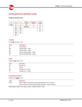
Code Description EM External flange - metric EU External flange - unified RM Reverse threaded flange - metric RU Reverse threaded flange - unified Code Description TM Threaded core - metric TU Threaded core - unified Code Description XXXX 25mm to 200mm full electrical stroke length selectable in 5mm increments 210mm to 500mm full electrical stroke length selectable in 10mm increments Stroke length is written as four digits e.g. 80mm = 0080 and 480mm = 0480
Open the catalog to page 3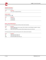
The ICT050 requires one of the following signal conditioning modules (ordered separately) EICT Corrosion resistant plastic enclosure sealed to IP66, with detail to fit rail DIN EN50022 or EN50035 or bulkhead mount via four M5 screws EICTM Powder coated metal enclosure sealed to IP68 with bulkhead mounting via four M5 screws The following accessories for the signal-conditioning module are also available (ordered separately) VM Voltage module output option card CM Current module output option card PWM Pulse width modulation output option card
Open the catalog to page 4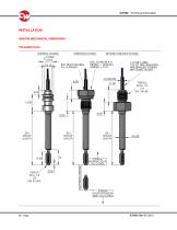
SENSOR MECHANICAL DIMENSIONS INTERNAL FLANGE THREADED FLANGE REVERSE THREADED FLANGE P67 REAR SEAL NG. METR O = 14.00rmn INTERNAL STOP OVER EXTENSION
Open the catalog to page 5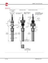
Sleeved Core
Open the catalog to page 6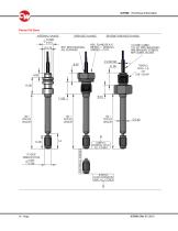
INTERNAL FLANGE REVERSE THREADED FLANGE DRILLED HOLE INTERNAL STOP,
Open the catalog to page 7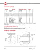
Item 12 (Label) is supplied for the customer to record ICT ordering code and is to be fitted in visible location adjacent to sensor for reordering reference Item 14, alternative cable gland seal, is supplied for connecting ICT050 direct to EICTM The installation details shown here are suggestions only because of the multiplicity of potential applications. The user should ensure that the design, method of assembly and materials used are satisfactory for the installation. Internal Flange Machining Details
Open the catalog to page 8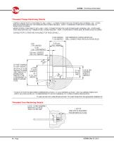
Threaded Flange Machining Details To seal use item 6 for unified thread and item 7 for metric thread from the appropriate installation kit Threaded Core Machining Details
Open the catalog to page 9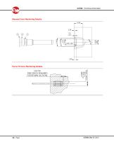
Sleeved Core Machining Details Force Fit Core Machining Details
Open the catalog to page 10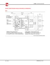
SIGNAL CONDITIONING MODULE MECHANICAL DIMENSIONS EICT Cover removed for illustrative purposes
Open the catalog to page 11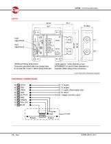
Bulkhead fixing dimensions Cable glands Cable diameter must Enclosure provided with four fixing holes be between 3.0 and 8.0mm diameter to to accept M5 screw x 30mm long minimum. maintain IP68 rating of the enclosure. Cover removed for illustrative purposes ELECTRICAL CONNECTIONS -O -V supply (Dual supply only) -O 0V return -O Voltage (current) output
Open the catalog to page 12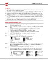
The green wire is internally connected to the transducer case. Due to the construction of the transducer external moving parts, the green connection should not be used as a ground connection. The enclosure is not connected internally to ground, so it can be mounted on a chassis carrying a voltage potential other than 0Vdc Misconnection of the supply may cause permanent damage. Maximum recommended distance between transducer and signal conditioning module is 10m. Each transducer is supplied with a sensor calibration module card (SCMC), calibrated to match the electrical stroke length. The EICT...
Open the catalog to page 13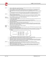
If using a voltage module, connect the VM card by inserting connector into position on header JP2 of EICT/EICTM PCB. Do not insert CM or PWM cards at this stage. Connect a DMM set to measure voltage to the output (terminal 5) and GND (terminal 6) on the EICT/EICTM PCB. Move the transducer core to the fully 'Lo' position (See Step 4 and Fig. 2) and power up the EICT/EICTM. Adjust ZERO trim pot until the required output voltage is achieved on the DMM display (0.5Vdc if no VM card is fitted in JP2). For Dual Supply option, output over the full range, relative to ground ('GND' 0V) will appear on...
Open the catalog to page 14
• EICT/EICTM must be disconnected from the transducer to carry out following check. • Using a DMM, set to the resistance range: • Measure between connections assigned to transducer 'yellow' and 'blue'. Value should lie between 400 and 1700. • Measure between connections assigned to transducer 'green' and 'yellow' and/or 'blue'. Value should be 'open circuit'. • Measure between connections assigned to 'green' and the transducer body. Value should be 'short circuit'. • 'Screen', if used - Connections assigned to 'screen' should be 'open circuit' to all the other electrical connections and transducer...
Open the catalog to page 15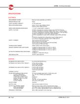
SPECIFICATIONS ELECTRICAL MEASUREMENT RANGE Maximum stroke selectable up to 500mm SENSOR RESOLUTION LEAST SQUARES LINEARITY INSULATION RESISTANCE Yellow / blue to case >50MΩ at 50Vdc Screen to case >50MΩ at 50Vdc GREEN WIRE BONDING RESISTANCE < 1+ (0.21 x cable length in metres) Ω SUPPLY VOLTAGE 10-60Vdc unregulated for standard voltage output (EICT/EICTM only) 10-30Vdc unregulated for extended voltage output group 1 (VM card fitted) 13.5-30Vdc unregulated for extended voltage output group 2 (VM card fitted) 10-30Vdc unregulated for current output (CM card fitted) 10-30Vdc unregulated for pulse...
Open the catalog to page 16All CURTISS-WRIGHT INDUSTRIAL DIVISION catalogs and technical brochures
 WM-H10
6 Pages
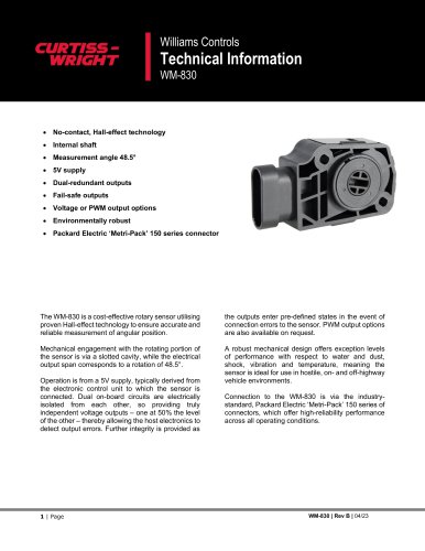 WM-830
7 Pages
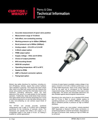 VPT351
11 Pages
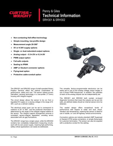 SRH301 & SRH302
11 Pages
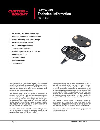 NRH300DP
11 Pages
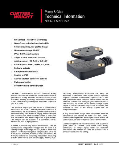 NRH271 & NRH272
13 Pages
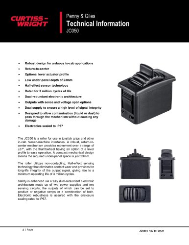 JC050
JC05011 Pages
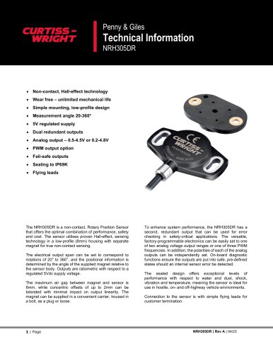 NRH305DR
11 Pages
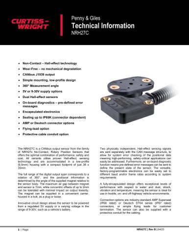 NRH27C
11 Pages
 JC8100
19 Pages
 JC040
JC04010 Pages
 JC8000
15 Pages
 JC1210
20 Pages
 ICT800 & ICT820
19 Pages
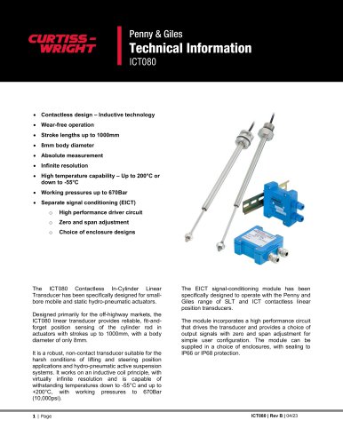 ICT080
15 Pages
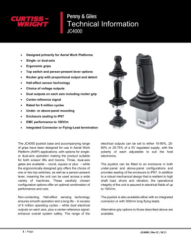 JC4000
23 Pages
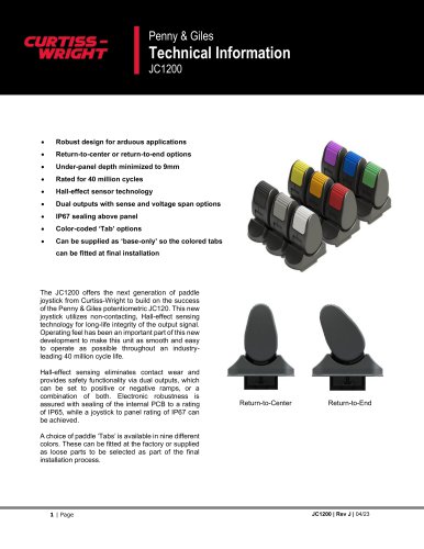 JC1200
12 Pages
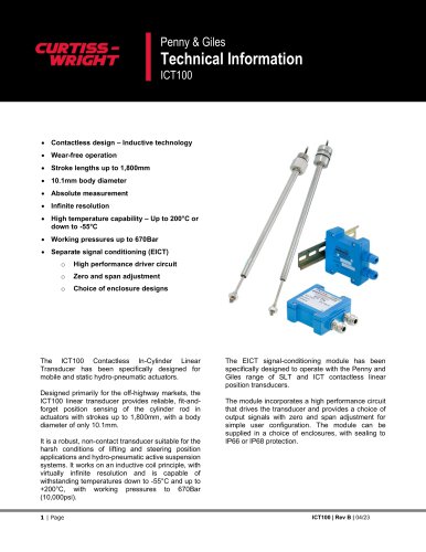 ICT100
15 Pages
 Rotary Position Sensors
6 Pages
 CWTI
CWTI4 Pages
 Industrial Division
4 Pages

- Electric actuator
- Single-pole switch
- Position transducer
- Tilt sensor
- HMI
- Control pedal
- Single pedal pedal
- Panel-mount HMI
- Electronic pedal
- Digital inclination sensor
- Rocker switch
- 2-axis tilt sensor
- No-contact position sensor
- Analog inclination sensor
- IP67 inclination sensor
- Compact position sensor
- Angular position sensor
- Single-axis joystick
- Compact switch