
- Catalogs
- Cubic Sensor and Instrument Co.,Ltd
- Cubic Outdoor Laser Particle Sensor Module PM3006S Specification

- Company
- Products
- Catalogs
- News & Trends
- Exhibitions
Cubic Outdoor Laser Particle Sensor Module PM3006S Specification
Cubic Outdoor Laser Particle Sensor Module PM3006S Specification
The PM3006S is an outdoor laser particle sensor module that uses laser scattering technology to measure particle mass concentrations (PM1.0, PM2.5, PM10, and TSP) in μg/m³. It features patented API technology for accurate measurements in various environments, with a quick response time of ≤8 seconds and an operating temperature range of -30℃ to 70℃.
- Patented intelligent automotive particle identification technology.
- High accuracy and sensitivity with constant current sampling.
- Real-time PM concentration output.
- Low noise cubic fan and durable laser diode.
- Optional UART and I²C signal outputs.
- Good EMC compatibility and strong antistatic ability.
- Measurement range: 0~1,000μg/m³, maximum display: 30,000μg/m³.
- Accuracy: PM1.0/PM2.5: ±5μg/m³ (<50ug/m3), ±10% (50~1000μg/m³); PM10: ±15μg/m³ (≤100μg/m³), ±15% (100~1000μg/m³).
- Data refresh time: 1 second; Time to first reading: ≤8 seconds.
- Power supply: DC 5V±0.1V, working current: <250mA, standby current: <25mA.
- Dimensions: W85*H74*D24.9 mm; Lifetime: ≥5 years.
The module includes a laser diode for particle detection, a photosensitive part for receiving scattered light, and an amplifier circuit. A microprocessor handles data processing and communication output.
The sensor uses an A2501WV-8P connector with a 2.5mm pitch. Key pins include power inputs (VCC, GND), UART/I²C communication pins (TXD/SCL, RXD/SDA), and a control pin for communication mode selection.
Configurations for UART TTL 3.3V and I2C TTL 3.3V outputs, compatible with 3.3V and 5V levels.
- UART protocol with a baud rate of 9600, data bits: 8, stop bits: 1, no parity.
- Commands include reading particle measurement results, opening/closing measurements, setting calibration coefficients, and reading software version and serial number.
The serial number is calculated using pairs of data fields (DF) as follows: Serial number = (DF1*256+DF2), (DF3*256+DF4), (DF5*256+DF6), (DF7*256+DF8), (DF9*256+DF10).
The sensor acts as a lower computer and is controlled by a main board. The I2C communication clock frequency is limited to 100Khz. Common signals include START, STOP, ACK, NACK, and data signals.
Dimensions of the sensor and accessories such as external heaters and ultrasonic flow meters are provided, along with their functions and measurement ranges.
Details on packaging include the number of sensors per tray and carton, carton dimensions, and packing material.
Installation guidelines emphasize ensuring unobstructed airflow and protecting sensor elements from dust. Recommended installation methods are illustrated.
Recommendations include using a protective filter at the air inlet, avoiding disassembly, and adhering to laser safety standards as the product is classified as a 3B laser product.
Contact information for Cubic Sensor and Instrument Co., Ltd is provided for further assistance.
Catalog excerpts
Product Name: Outdoor Laser Particle Sensor Module Item No.: PM3006S Version: V0.1 Date: August 18, 2020
Open the catalog to page 1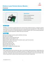
Outdoor Laser Particle Sensor ModulePM3006S Applications ■ Outdoor Air Quality Monitoring ■ Construction Site Monitoring ■ M i ning Site Monitoring PM3006S is a linear light source-based particle sensor module with laser scattering technology. It is designed to measure the quantity per unit volume of different particle size and can output particle mass concentration PM1.0, PM2.5, PM10 and TSP in gg/m3 at the same time via mathematical algorithm and scientific calibration. Built-in Cubic auto particle identification technology for accurate measurement in different dust source environment. ■ Patented...
Open the catalog to page 3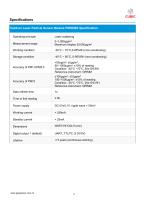
Specifications Outdoor Laser Particle Sensor Module PM3006S Specification
Open the catalog to page 4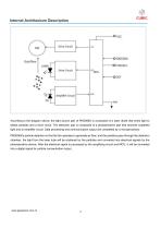
Dnve Circuit Dust flow Amplifier Circuit According to the diagram above, the light source part of PM3006S is composed of a laser diode that emits light to detect particles and a drive circuit. The detection part is composed of a photosensitive part that receives scattered light and an amplifier circuit. Data processing and communication output are completed by a microprocessor. PM3006S's particle detection is that the fan operates to generate air flow, and the particles pass through the detection chamber, the light from the laser tube will be scattered by the particles and converted into electrical...
Open the catalog to page 5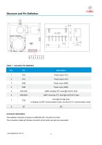
Structure and Pin Definition Table 1. Connector Pin Definition Connector Description The interface connector of sensor is A2501WV-8P. The pitch is 2.5mm. The connection cable with female connector at both ends can also be customized.
Open the catalog to page 6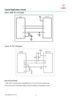
Case 2. I2C TTL 3.3V Output Note of Circuit Design ■ UART and I2C communication compatibility with 3.3V and 5V level (receiving end). ■ Pin 8 is the pin for manufacturer testing, should be floating in the application circuit.
Open the catalog to page 7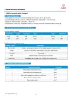
Communication Protocol♦ UART Communication Protocol1. General Statement 1) The data in this protocol is all hexadecimal data. For example, “46” for decimal [70]. 2) [xx] is for single-byte data (unsigned, 0-255); for double data, high byte is in front of low byte. 3) Baud rate: 9600; Data Bits: 8; Stop Bits: 1; Parity: No 4) It is default by continuously mode after powering on. Working mode will not be saved after powering off. Sending format of software:
Open the catalog to page 8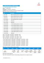
4.1 Read Particle Measurement Result Function: Read concentration of particle and particles number. Note: Read particle concentration (ug/m3)_ DF49: Alarm of sensor module working condition: 1. Laser tube failure alarm temperature temperature revolving revolving alarm alarm Note: Part of reserved bit is used for internal testing. Reserved bit is not related to function www.gassensor.com.cn
Open the catalog to page 9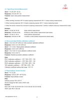
4.2 Open/Close Particle Measurement Send: 11 03 0C DF1 1E CS Response: 16 02 0C DF1 CS Function: Open/ close particle measurement Note: 1. When sending command, DF1=2 means opening measurement, DF1=1 means closing measurement; 2. When receiving response, DF1=2 means measuring opened, DF1=1 means measuring closed; 3. When the sensor receives the command of opening measurement, it will be in default continuous measurement mode. Example: Send: 11 03 0C 02 1E C0 //open particle measurement //module is under particle measurement open status //close particle measurement // module is under particle...
Open the catalog to page 10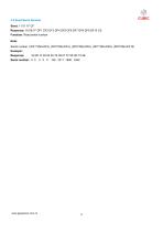
4.5 Read Serial Number
Open the catalog to page 11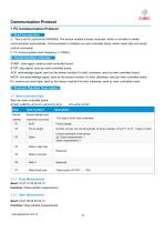
Communication Protocol♦ I2C Communication Protocol1. Brief Introduction a. This is an IIC protocol for PM3006S. The sensor module is lower computer, which is not able to initiate communication automatically. Communication is initiated via main controlled board, which reads data and sends control commands. b. I2C communication clock frequency <=100Khz START: start signal, send by main controlled board; STOP: stop signal, send by main controlled board; ACK: acknowledge signal, send by the sensor module if in bold; otherwise, send by main controlled board; NACK: non-acknowledge signal, send by the...
Open the catalog to page 12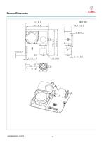
Sensor Dimension
Open the catalog to page 14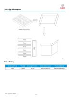
Package Information Table 3. Packing
Open the catalog to page 16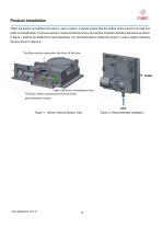
Product Installation When the sensor is installed and used in user’s system, it should ensure that the airflow at the sensor’s air inlet and outlet is unobstructed. To ensure sensor’s measurement accuracy, the surface of sensor sensitive elements as shown in figure 1 shall be protected from dust depositing. It is recommended to install the sensor in user’s system following the way shown in figure 2. Figure 1. Sensor Internal Section View Figure 2. Recommended install
Open the catalog to page 17
User Attentions ※ The air inlet inside diameter of user equipment should not be less than the sensor’s air inlet diameter ※ When use the product, it is recommended to add a 50-60 mesh protective filter to the sensor's air inlet to prevent flocs, hair, etc. from affecting the sensor's detection. ※ The product is an integral unit that shall not be disassembled to avoid any irreversible damages. ※ This product is defined as 3B laser product according to GB7247.1-2012 Laser Product Safety with laser radiation inside. Please avoid direct illumination on the eye. The warning signs are as follows: After-Sales...
Open the catalog to page 18All Cubic Sensor and Instrument Co.,Ltd catalogs and technical brochures
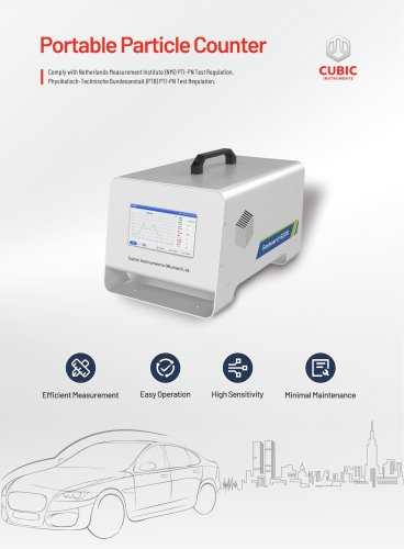
 Portable Particle Counter
2 Pages
 Cubic TDLAS CH4 Sensor
4 Pages
 Gasboard-7500H-OPC
13 Pages
 NDIR CO2 Sensor Module-CM1106LS
18 Pages
 Laser Particle Sensor-PM2008M-M
22 Pages
 Laser Particle Sensor-PM2012
19 Pages
 Test Instruction of AM4100-I
7 Pages
 Test Instruction of AM1008W
7 Pages
 Test Instruction of PM5000
7 Pages
 Test Instruction of PM1006
8 Pages
 Test Instruction of CM1107T
7 Pages
 Test Instruction of CM1107BN
8 Pages
 Test Instruction of PM3006T
7 Pages
 Test Instruction of PM2009
8 Pages
 Test Instruction of CM1106SH
8 Pages
 Test Instruction of CM1107
8 Pages
 Test Instruction of CM1106S
8 Pages
 Test Instruction of CM1106LS
8 Pages
 Laser Particle Sensor-PM2008
21 Pages
 Laser Particle Sensor-PM2009
20 Pages
 Laser Particle Sensor-PM2105-M
20 Pages
 NDIR CO2 Sensor Module-CM1106S
18 Pages
 Gas Sensor Line-up
1 Page
 About Cubic
1 Page
 CEMS Solution - Gasboard 9050
22 Pages
 NDIR CO2 Sensor Modules
7 Pages
 Gasboard-7020
4 Pages
 Gasboard-7500
7 Pages
 Mainstream ETC02 module
5 Pages
 Gasboard 3400P
5 Pages
 Analyzer Gasboard 3800P
6 Pages
 LANDFILL APPLICATIONS
8 Pages




















Archived catalogs
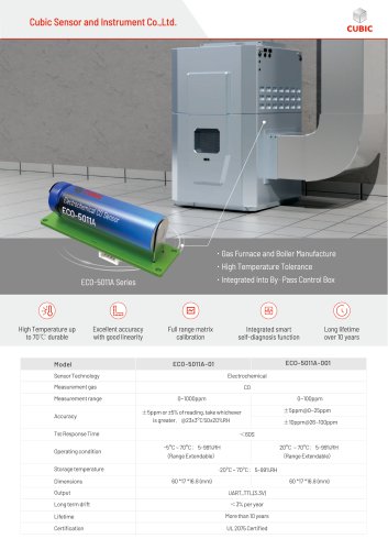 Cubic CO Sensor Brochure
2 Pages
 Air quality monitor AM7000
11 Pages
 RHB Series
8 Pages
 Syngas portable analyzers
4 Pages
 Opacity meter
1 Page
 Infrared Methane gas sensor
3 Pages


- Cubic volume flow meter
- Liquid flow monitor
- Cubic gas analyzer
- Cubic concentration analyzer
- Cubic monitoring analyzer
- Cubic liquids analyzer
- Measuring machine
- Cubic automatic analyzer
- Calibration system
- Cubic waterproof flow meter
- Cubic gas flow meter
- Benchtop analyser
- Cubic solids analyzer
- Stainless steel flow monitor
- Air blower
- Industrial flow monitor
- Cubic process analyzer
- Gas detector
- Pressure probe