 Website:
CubeMars
Group: CubeMars
Catalog excerpts
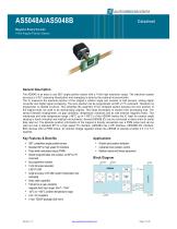
Magnetic Rotary Encoder 14-bit Angular Position Sensor General Description The AS5048 is an easy to use 360° angle position sensor with a 14-bit high resolution output. The maximum system accuracy is 0.05° assuming linearization and averaging is done by the external microcontroller. The IC measures the absolute position of the magnet’s rotation angle and consists of Hall sensors, analog digital converter and digital signal processing. The zero position can be programmed via SPI or I²C command. Therefore no programmer is needed anymore. This simplifies the assembly of the complete system because the zero position of the magnet does not need to be mechanically aligned. This helps developers to shorten their developing time. The sensor tolerates misalignment, air gap variations, temperature variations and as well external magnetic fields. This robustness and wide temperature range (-40°C up to +150°C) of the AS5048 makes the IC ideal for rotation angle sensing in harsh industrial and medical environments. Several AS5048 ICs can be connected in daisy chain for serial data read out. The absolute position information of the magnet is directly accessible over a PWM output and can be read out over a standard SPI or a high speed I²C interface. AS5048A has a SPI interface, AS5048B I2C interface. Both devices offer a PWM output. An internal voltage regulator allows the AS5048 to operate at either 3.3 V or 5 V supplies. 360° contactless angle position sensor Standard SPI or high speed I²C interface Pulse width modulated output (PWM) Simple programmable zero position via SPI or I²C command No programmer needed 14-bit full scale resolution 0.0219°/LSB Angle accuracy 0.05°after system linearization and averaging Daisy chain capability Tolerant to air gap variations magnetic field input range: 30mT – 70mT -40°C to +150°C ambient temperature range 3.3V / 5V compliant 14-pin TSSOP package (5x6.4mm) • Robotic joint position detection • Industrial motor position control • Medical robots and fitness equipment Block Diagra
Open the catalog to page 1
Magnetic Rotary Encoder 14-bit Angular Position Sensor
Open the catalog to page 2
Magnetic Rotary Encoder 14-bit Angular Position Sensor 6.3 6.4 6.5 List of Figures F IGURE F IGURE F IGURE F IGURE F IGURE F IGURE F IGURE F IGURE F IGURE F IGURE F IGURE F IGURE F IGURE F IGURE F IGURE F IGURE F IGURE F IGURE List of Tables T ABLE T ABLE T ABLE T ABLE T ABLE T ABLE T ABLE T ABLE T ABLE T ABLE T ABLE
Open the catalog to page 3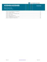
Magnetic Rotary Encoder 14-bit Angular Position Sensor T ABLE T ABLE T ABLE T ABLE T ABLE T ABLE T ABLE
Open the catalog to page 4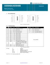
Magnetic Rotary Encoder 14-bit Angular Position Sensor SPI chip select - active low DIO_ST SPI master in/slave out DIO_OD Data pin I2C interface Positive Supply Voltage, 3.0 to 5.5 V 3.3V Regulator output; internally regulated from VDD. Connect to VDD for 3V supply voltage. 10 F capacitor to GND required in 5V operation mode Negative Supply Voltage (GND) Pulse Width Modulation output Table 1: Pin description TSSOP14 supply pad analog I/O digital input with schmitt trigger digital output – push-pull digital I/O with schmitt trigger in the input path digital I/O with open drain output Note:...
Open the catalog to page 5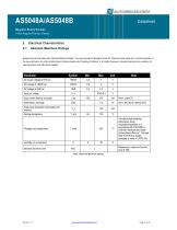
Magnetic Rotary Encoder 14-bit Angular Position Sensor Electrical Characteristics Absolute Maximum Ratings Stresses beyond those listed under “Absolute Maximum Ratings“ may cause permanent damage to the device. These are stress ratings only. Functional operation of the device at these or any other conditions beyond those indicated under “Operating Conditions” is not implied. Exposure to absolute maximum rating conditions for extended periods may affect device reliability. Input current (latchup immunity) Electrostatic discharge Total power dissipation (all supplies and outputs) Storage...
Open the catalog to page 6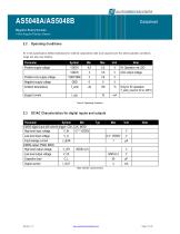
Magnetic Rotary Encoder 14-bit Angular Position Sensor Operating Conditions All in this specification defined tolerances for external components need to be assured over the whole operation conditions range and also over lifetime. Positive supply voltage Ambient temperature Supply Current Positive core supply voltage Negative supply voltage Only for 5V operation. T_amb_max for 3V is 125°C Table 3: Operating Condition DC/AC Characteristics for digital inputs and outputs Parameter Symbol Min CMOS digital input with schmitt trigger: CSn, CLK, MOSI High level input voltage V_IH 0.7 * VDD5V Low...
Open the catalog to page 7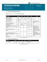
Magnetic Rotary Encoder 14-bit Angular Position Sensor Electrical System Specifications VDD5V = 5V, TAmbient = -40 to +150°C unless noted otherwise Parameter Magnetic input field Output sampling rate Output Resolution Sensor output noise System propagation delay Assuming 8 mm diameter of magnet Assuming 8 mm diameter of magnet and 500 um displacement in x and y Assuming 8 mm diameter of magnet and 500 um displacement in x and y Non-linearity optimum placement of magnet Non-linearity @displacement of magnet Non-linearity @displacement of magnet and temperature -40 -150 degC Startup Time...
Open the catalog to page 8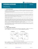
Magnetic Rotary Encoder 14-bit Angular Position Sensor Functional Description The AS5048 is a magnetic Hall sensor system manufactured in a CMOS process. A lateral Hall sensor array is used to measure the magnetic field components perpendicular to the surface of the chip. The AS5048 is uses self-calibration methods to eliminate signal offset and sensitivity drifts. The integrated Hall sensors are placed around the center of the device and deliver a voltage representation of the magnetic flux Bz. Through Sigma-Delta Analog-to-Digital Converter (ADC) and Digital Signal-Processing (DSP)...
Open the catalog to page 9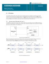
Magnetic Rotary Encoder 14-bit Angular Position Sensor The 16 bit SPI Interface enables read / write access to the register blocks and is compatible to a standard micro controller interface. The SPI is active as soon as CSn is pulled low. The AS5048A then reads the digital value on the MOSI(master out slave in) input with every falling edge of CLK and writes on its MISO (master in slave out) output with the rising edge. After 16 clock cycles CSn has to be set back to a high status in order to reset some parts of the interface core. SPI Interface Signals (4-Wire Mode, Wire_mode = 1) The...
Open the catalog to page 10All CubeMars catalogs and technical brochures
-
Underwater Thruster
7 Pages
-
ROBOTIC MOTOR SOLUTION
76 Pages
Archived catalogs
-
CubeMars Introduction
20 Pages
-
CubeMars-Catalogue new
27 Pages


