
Catalog excerpts
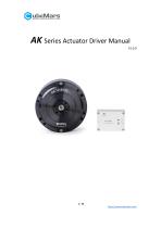
AK Series Actuator Driver Manual
Open the catalog to page 1
CONTENT Content -------------------------------------------------------------------------------------------------------------- 2 Notice ---------------------------------------------------------------------------------------------------------------- 4 Feature ---------------------------------------------------------------------------------------------------------------5 Disclaimer ----------------------------------------------------------------------------------------------------------- 5 Version Change Record...
Open the catalog to page 2
5. Driveboard Communication Protocol and Description ----------------------------------------------32 5.1 Servo Mode Control and Description ---------------------------------------------------------------32 5.1.1 Duty Cycle Mode -----------------------------------------------------------------------------------34 5.1.2 Current Loop Mode ------------------------------------------------------------------------------- 34 5.1.3 Current Brake Mode ------------------------------------------------------------------------------ 35 5.1.4 Velocity Loop Mode...
Open the catalog to page 3
Notice 1. Ensure that the circuit is normal and the interface is correctly connected as required. 2. The driver board will be hot when output, please use it carefully to avoid burns. 3. Please Check whether the parts are in good condition before use. If any parts are missing or aging, please stop using and contact technical support in time. 4. Several optional control modes can’t be switched when driver board is working, and different control mode have different communication protocol. If you need to switch, please reboot the power to the diver board then to change. Using the wrong protocol...
Open the catalog to page 4
Feature The AK series actuators’ driver board adopts the driver chip with highperformance, uses the Field Oriented Control (FOC) algorithm, and is equipped with advanced active disturbance rejection control technology to control the speed and angle. It is matched with our modular motor to form a powerful power package. It can be used with CubeMars Tool assistant software for parameter setting and firmware upgrade. Disclaimer Thank you for purchasing the AK series actuators. Before using, please read this statement carefully. Once used, it is deemed to be an endorsement and acceptance of the...
Open the catalog to page 5
permission, it is not allowed to reproduce in any form. The final interpretation right of the disclaimer belongs to JIANGXI XINTUO ENTERPRISE CO., LTD. Version Change Record Date Change content create version Correct data definitions of 5.1,5.2 and 5.3 UART protocol update of 5.2 motor speed in 5.3 Add the Servo Mode Serial Message Protocol in 5.2 Add some explain of the Servo Mode Serial Message Protocol in 5.2
Open the catalog to page 6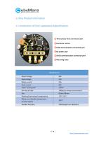
1.Drive Product Information 1.1 Introduction of Drive' appearance &Specifications ①Three-phase wires connection port ②Hardware version ③CAN communication connection port ④DC power port ⑤Serial communication connection port ⑥Mounting holes Specifications Rated Voltage Peak Voltage Rated current Peak current Power consumption Working Environment temperature Maximum allowable temperature of driver board Encoder Accuracy
Open the catalog to page 7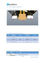
1.2 Drive Interface and Definition 1.2.1 Drive Interface Diagram 1.2.2 The Brand and Model of Drive Interface No. Onboard interface model Wire interface model 1.2.3 Drive Interface pin Definition No. 1 Interface function Serial communication Explain Serial signal ground(GND) 8 / 52
Open the catalog to page 8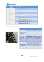
Interface function Positive pole(+) CAN communication low side (CAN_L) CAN communication high side(CAN_H) CAN communication high side(CAN_H) Negative pole(-) POWER INPUT Serial signal input(RX) Serial signal output (TX) CAN communication low side (CAN_L) 1.3 Drive Indicator Definition Indicator definition The power indicator is used to show the power supply of 1.Power indicator(when blue light is on) the driver board. Normally, it will light up blue when the power is plugged in. If the blue light is not on, please remove the power immediately and never turn on the power again. The...
Open the catalog to page 9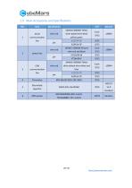
1.4 Main Accessories and Specifications NO. Item Serial communication line 24AWG-300MM-Teflon silver-plated wire-black yellow green 24AWG-300MM-Teflon silver-plated wire-white and blue Electrolytic capacitor
Open the catalog to page 10
2. R-link produce information 2.1 Introduction of R-link' appearance&Specifications Specification Rated Voltage Power consumption Working Environment temperature Maximum allowable temperature of board
Open the catalog to page 11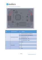
2.2 R-link Interface and Definition Interface function Serial signal output (TX) Serial signal ground(GND) VBUS Serial signal input(RX) Communication Interface CAN communication high side(CAN_H)
Open the catalog to page 12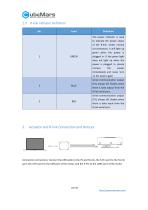
2.3 R-link Indicator Definition No. The power indicator is used to indicate the power status of the R-link. Under normal circumstances, it will light up green when the power is plugged in. If the green light does not light up when the power is plugged in, please remove the power immediately and never turn on the power again Serial communication output (TX), always off, flashes when there is data output from the R-link serial port. Serial communication output (TX), always off, flashes when there is data input from the R-link serial port. Actuator and R-link Connection and Notices Connection...
Open the catalog to page 13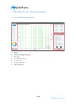
4. Instructions for use of the upper computer 4.1 PC interface and instruction Home Chinese and English Switching Main page Implement data display Current mode Serial port selection control parameter
Open the catalog to page 14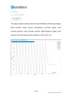
4.1.1 Home 4.1.1.1 waveform display This page supports viewing real-time data feedback and drawing images. Data includes: motor current, temperature, real-time speed, inner encoder position, outer encoder position, high-frequency speed, rotor position, path planning, position deviation, DQ current, etc.
Open the catalog to page 15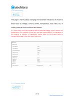
This page is mainly about changing the hardware limitations of the drive board such as voltage, current, power, temperature, duty ratio, etc. It mainly protects the drive board and motors. ⚠: Please use it strictly in accordance with the specified voltage, current, power, and temperature. Our company will not bear any legal responsibility if the operation of this product in violation of regulations causes injury to the human body or irreversible damage to the drive board and motor.
Open the catalog to page 16All CubeMars catalogs and technical brochures
-
CubeMars Introduction
20 Pages
-
CubeMars-Catalogue new
27 Pages
-
AS5084A encoder
29 Pages


