

- Products
- Catalogs
- News & Trends
- Exhibitions
CID V2.01

CID V2.01
The CID-PRO system requires Windows 95, 98, XP, Me, NT 4.0, or 2000, a Pentium processor (90MHz minimum, 350MHz recommended), a 3.5’’ floppy disk drive, a free serial interface, a parallel interface for a hardware key, a mouse, a VGA video adapter (256 colors, 640 x 480 pixels), at least 64MB of memory, and 100 MB of free disk space.
Insert the installation disk into the floppy drive, exit all Windows programs, and run 'a:setup'. Confirm installation directories and back up data before installation. For updates, select the current CID directory.
Install the driver software for the hardware key on the LPT1 port, restart the system, and configure chambers by entering their number, port, and scan intervals.
Includes Status, Overview, Editor, Graphics, Auto, Recording, Config, Cycles, and Report masks, each serving specific functions like displaying chamber status, creating cycles, and managing data.
CID-PRO interfaces with Microsoft WinWord and Excel for document and data management.
Features a TCP/IP module for networking and monitoring over a LAN network.
Procedures for managing errors include checking chambers for potential causes and resetting the control panel if locked.
Users can create and modify test cycles, set parameters, and assign wait functions. Software limits prevent exceeding chamber ranges.
Users can create, save, load, and delete test programs, with options for printing cycles.
Includes service symbols for detailed chamber information and options for adjusting time scales and grid precision.
Instructions for programming loops, including setting start and end points and changing loop counts.
Background programs must exist before creating the main program and cannot overlap.
Allows branching based on digital input signals, acting like an interrupt.
Provides graphical representation and analysis of measurements, with options for customization and printing.
Cycles can be transmitted to a selected chamber, with options for starting time and cycle offset.
Details on starting and managing recordings, including setting intervals and selecting filenames.
Covers communication settings, sampling frequency recommendations, and password protection.
Preferences allow changes to window sizes, while special configurations involve editing the 'cid_pro.ini' file.
Explains how to view and modify time and round counters, and manage reports.
Details how power failures are reported, with a list of up to 10 entries showing ON and OFF durations.
Users can configure email alerts for specific events, requiring internet access and an SMTP server.
Facilitate rapid temperature changes, with options to start or create programs for these chambers.
Help is accessible throughout CID-PRO by right-clicking on buttons or pressing 'F1'.
Users can insert CID-PRO masks into WINWORD documents and resize graphics.
Measurements can be converted to a format readable by EXCEL using the CID-->EXCEL conversion program.
CID software supports networking chambers over a LAN using TCP/IP.
Instructions for setting up CID software on server and client PCs, including editing the 'cid_pro.ini' file.
Outlines configuration for remote control of chamber 1, specifying it as a data client with a unique IP port.
Instructions for configuring the cid_pro.ini file to store data on a network.
Supports data exchange with other applications via TCP/IP.
In case of power cuts, CID-PRO attempts to restore the previous status, with recovery details logged in a report file.
Includes an extensive index covering various features and mentions the availability of online help and service information.
Catalog excerpts
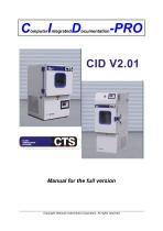
omputer ntegrated Manual for the full version Copyright National Instruments Corporation. All rights reserved
Open the catalog to page 1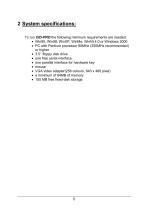
To run CID-PRO the following minimum requirements are needed: • Win95, Win98, WinXP, WinMe, WinNt 4.0 or Windows 2000 • PC with Pentium processor 90MHz (350MHz recommended) or higher • 3.5’’ floppy disk drive • one free serial interface • one parallel interface for hardware key • mouse • VGA video adapter(256 colours, 640 x 480 pixel) • a minimum of 64MB of memory • 100 MB free fixed-disk storage
Open the catalog to page 5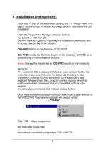
Place the 1st disk of the installation set into the 3.5'' floppy drive. It is highly recommended to exit all window programs before starting the installation. From the Programme Manager, choose file Run. Type a:setup and click OK. Confirm the interrogations regarding the installation directories with a mouse click on the ‘finish' button. CID-PRO itself is in the directory /CTS_SOFT. CID-PRO installs the Runtime Engine in the directory /CVIRTE as a subdirectory of the installation directory. Never change the directories as CID-PRO would not run correctly. UPDATE: IF a version of CID is already...
Open the catalog to page 6
Uninstall..: Uninstallation programme. The programme deletes the group CID-PRO in the Programme Manager. Also all the programme files, but the files they are created during the work with CID-PRO such as report files and measurements, also ini-files are preserved. If you really never need any more files you can delete all of the files in the installation directory of CID-PRO.
Open the catalog to page 7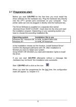
Before you start CID-PRO for the first time you must install the driver software for the hardware key. Plug the hardware key directly onto the LPT1 (printer port) connection on your computer. Your printer cable can now be plugged in directly onto the hardware key. The Driver Software is supplied on a separate disk named „Sentinel Driver WinNT & Win95“. Insert disk into the drive and start the installation program. Depending on your operating system you have to choose the according installation file. In the Installation choose out the function „Install Sentinel Driver11. Confirm the displayed...
Open the catalog to page 8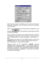
Enter here the amount of chambers you have, the port that they have been connected to and the intervals at which the chambers must be scanned. Switch on your chamber(s) and proceed with the configuration using this button . This procedure can take several minutes (2-3 min. per chamber). Don’t you get any connection to the chamber(s), please control the communication protocol. To do this: type ‘E’ ‘P’ ‘P’: now you had to see in the upper LCD ‘CID’, when not: toggle to ‘CID’ with the + / keys.. The number in the lower LCD is the address which is used in the CID-PRO. Maybe you have to adjust the...
Open the catalog to page 9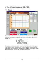
Status of the active chamber can be seen on the status mask. The chamber number and designation are shown in the upper right-hand corner: e.g. C03 C-10/350 Chamber: 3 is active Designation: C-70/350 The status window is sizeable. Using the maximize button in the upper right-hand corner of the title bar the window expands to size of screen. The menus are optimised for resolutions for 640x480 to 1024x768 pixels. Enlargement may result in little distortion of the screen.
Open the catalog to page 10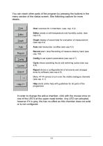
You can reach other parts of the program by pressing the buttons in the menu section of the status screen. See following capture for more details. Over overview for 4 chambers (see. cap. 4.2) Editor create or edit temperature and humidity cycles. (see cap.4.3) Graph display of saved data for evaluation of measurement (see cap.4.4) Auto start testcycles / profiles (see cap.4.5 ) Record start / stop Recording of measure data by hand (see cap. 4.6) Config to set system parameters (see cap.4.7) Cycle shows operating hours and switching cycles (see cap 4.8) Report shows a configurable list of all...
Open the catalog to page 11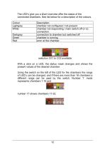
The LED’s give you a short overview offer the status of the connected chambers. See list below for a description of the colours. selection C01 to C03 available With a click on a LED, the status mask changes and shows the present values of the desired chamber. Using the switch on the left of the LED for the chambers the range of LED’s can be changed, and if there are more than 16 chambers a different range can be used by this switch. Number ‘1’ mode represents chambers 1-16 and number 17 shows chambers 17-32.
Open the catalog to page 12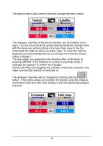
The status mask is also used to manually change the index values. The analogue channels of the active chamber can be modified in two ways. You can move the arrow symbol directly below the channel name with the mouse as well as putting in the new index value in the box underneath the slides to set a new index value. To enter the value by keyboard you must activate the box by clicking into it with the mouse (colour changes). The new values are assigned to the chamber after confirmation by pressing ‘ENTER’. If the chamber is running in automatic-mode a message box appears to confirm the changes....
Open the catalog to page 13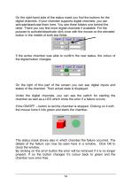
On the right-hand side of the status mask you find the buttons for the digital channels. If your chamber supports digital channels, you can activate/deactivate them here. You see three folders one behind the other. There you can find more digital channels if available. For the purpose to activate/deactivate click once with the mouse on the elevated button in the middle of both text fields. If the active chamber was able to confirm the new status, the colour of the digital button changes. On the right of this part of the screen you can see digital inputs and states of the chamber. Their actual...
Open the catalog to page 14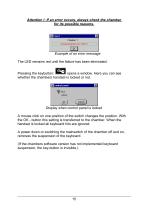
Attention !: If an error occurs, always check the chamber for its possible reasons. Example of an error message The LED remains red until the failure has been eliminated. Pressing the keybutton: opens a window. Here you can see whether the chambers handset is locked or not. Display when control panel is locked A mouse click on one position of the switch changes the position. With the OK - button this setting is transferred to the chamber. When the handset is locked all keyboard hits are ignored. A power down or switching the mainswitch of the chamber off and on, removes the suspension of the...
Open the catalog to page 15All CTS Clima Temperatur Systeme GmbH catalogs and technical brochures
 VOC emission test chamber EK1000
12 Pages
 G1 Control
6 Pages
 CDI V4.02
174 Pages
 CID V300
88 Pages
 Environmental Simulation
7 Pages
 CTS Climatic Test Cabinets
2 Pages
 CTS Shocktest cabinet
2 Pages
 Customised Solutions
8 Pages

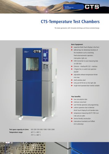
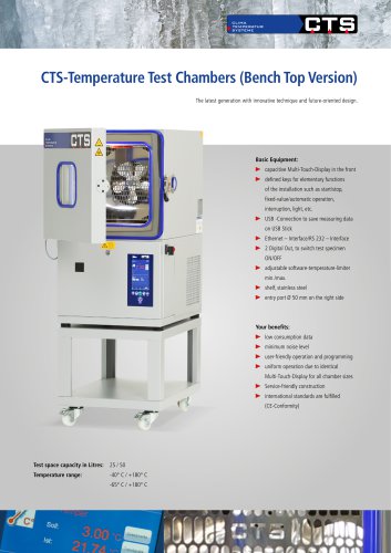
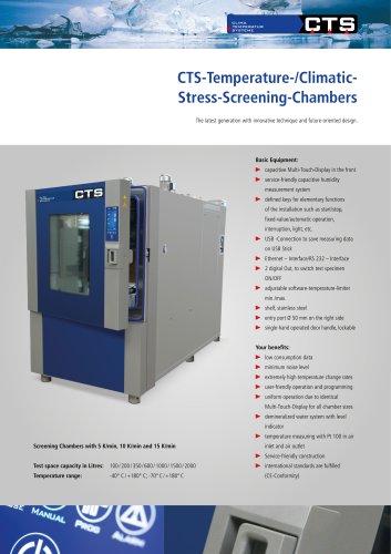
- CTS Clima Temperatur Systeme test chamber
- CTS Clima Temperatur Systeme temperature test chamber
- CTS Clima Temperatur Systeme climate chamber
- CTS Clima Temperatur Systeme quality control test chamber
- Humidity test cabinet
- Environmental test chamber
- Stainless steel test chamber
- Floor-standing test chamber
- CTS Clima Temperatur Systeme test chamber with window
- LED test chamber
- Test chamber for the aeronautical industry
- Battery test chamber
- Aging test chamber
- Electrical equipment test chamber
- Thermostatic test chamber
- Simulation test chamber
- European standards-compliant test chamber
- Compact test chamber
- Material test chamber
- Solar panel test chamber