Catalog excerpts
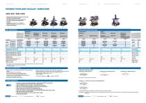
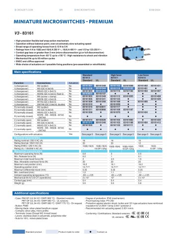
| MANUALLY OPER ATED SWITCHES | MANUALLY OPER ATED SWITCHES PUSHBUTTONS AND TOGGLES - MINIATURE 8350 / 8351 / 8352 / 8353 › ouble-break flexible leaf snap-action mechanism D › omentary or maintained action M › hangeover-SPDT microswitch as standard C › ne, two and three-pole configurations O › ong life L › atings from 10 mA 4 Vc to 10 A 250 Va R › perating temperature -40 °C up to +125 °C O › hoice of connections C Main specifications Main specifications (continued) Pushbuttons Action Features Function Connections I (changeover) W1 (screw) 1-pole I (changeover) W2 (solder) (835--0) I (changeover) W3 (QC 6.3x0.8) I (changeover) W1 (screw) 2-pole I (changeover) W2 (solder) (835--3) I (changeover) W3 (QC 6.3x0.8) Electrical characteristics Rating nominal / 250 V AC (A) Rating thermal / 250 V AC (A) Mechanical characteristics Maximum operating force, 1-pole (N) Maximum operating force, 2-pole (N) Maximum total travel force, 1-pole (N) Maximum total travel force, 2-pole (N) Pretravel (mm) Total travel (mm) Ambient operating temperature (°C) Mechanical life (operations) Weight, 1-pole (g) Weight, 2-pole (g) Momentary Standard Tandem buttons Momentary + Maintained* Long travel Long travel Long travel Metal plunger Recessed button 3 positions Auto-return to center Momentary + Maintained ** 3 positions Auto-return to center on momentary side 83517 Action Features Func. Conn. I W1 1-pole I W2 (835--0) I W3 I W1 2-pole I W2 (835--3) I W3 Electrical Nom rating (A) Therm rating (A) Mechanical OF max, 1p (N) OF max, 2p (N) TTF max, 1p (N) TTF max, 2p (N) PT (mm) TT (mm) Temp (°C) Mech. life (op) Weight, 1p (g) Weight, 2p (g) * Push slightly for momentary action. Fully push for maintained action, to latch, then to unlatch ** One side momentary, the other side maintained *** Please consult us Additional specifications - uttons, toggles: POM, PA66 (83502, 83507), nickel-plated brass B (83522) - ounting brackets: zinc-plated steel M - arrels, knurled bezels, nuts: nickel-plated brass B - utton collars: chrome-plated ABS (83533, 83535) B - ontacts: silver alloy (gold-plated silver alloy: on request) C - erminals: brass, copper nickel (W2) T - ealing cap (accessory): silicone rubber S Double break snap-action switch - egree of protection: IP40 (button side), IP50 with cap (accessory) D - rotection against electric shock: Class I (see also “installation recommendations”) P - ated insulation voltage Ui: 250 V (for Ui 400 V, please consult us) R - mpulse withstand voltage Uimp: 2.5 kV I - ollution degree: 3 P - Conformity / Certifications: Normally closed - SPST-NC (form Y) Normally open - SPST-NO (form X) on request / Both circuits must be used at same polarity Product adaptations Changeover - 2 x SPDT (2 x form Za): for 83515/83516/83517 › unctions on request: normally closed (R) or normally open (C) SPST microswitches F › -pole configurations: 835--6 (except for 83515, 83516, 83517) 3 › igh DC switching capacity: 5 A 250 Vc (with 83154 microswitches) H › ual-current variants with gold-plated contacts for use from 10mA to 5A D › uilt-in screw connections (with 83112 microswitches) B › older connections on front face (with 83109 microswitches) S › ealing cap accessory for IP50 protection on button side (for 83502, 83507, 83513, 83553) S › ed button on 83507 and 83535 models R › igh operating temperature: +125 °C (on 83507, 83513, 83522) H › URus approved models c Standard product Changeover - SPDT (form Za): Product made to order As standard: each SPDT microswitch is operated by one lever maximum position As adaptation: oth SPDT microswitches can be simultaneously oper
Open the catalog to page 1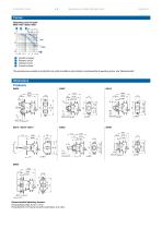
| MANUALLY OPER ATED SWITCHES Curves Operating curve for types 8350 / 8351 / 8352 / 8353 2 Number of cycles Resistive circuit Inductive circuit Current in Amps The operating curve relates to contact life, but switch durability is also limited by mechanical life of operating device: see “Mechanical life” Recommended tightening torques: Fixing by M3 screws: 0.8 to 1.2 N.m Fixing by M12 x 0.75 barrel nut and knurled beze: 2 to 4 N.m
Open the catalog to page 2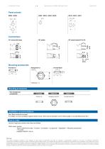
| MANUALLY OPER ATED SWITCHES Connections W1 screw with clamp Mounting accessories Knurled nut Knurled bezel Mounting accessories Part numbers for accessories Installation recommendations See “Basic technical concepts” For 83522: to ensure protection against electric shock, direct manual operation on the metal plunger is not permitted above 48 V. How to order Use the 8 digit part numbers when they are defined Other cases, precise: T ype of switch/nb of poles - Function - Connection - UL approval* - Adaptation* + Mounting accessories* * if needed Example: 835073 I W3 UL Warning: The...
Open the catalog to page 3All Crouzet catalogs and technical brochures
-
Analog expansion E10A
5 Pages
-
GN4 Series
6 Pages
-
GN2 Series
8 Pages
-
MOTORS & GEARMOTORS
5 Pages
-
SWITCHES & PROXIMITY SENSORS
5 Pages
-
Tk2R1
3 Pages
-
MLS2
3 Pages
-
MLR1
4 Pages
-
Mus2
4 Pages
-
AUTOMATION & CONTROL
6 Pages
-
MCR1
3 Pages
-
MAR1
4 Pages
-
MUR1
4 Pages
-
Millenium 3
3 Pages
-
Compact prewired limit switch
10 Pages
-
8D 4R 24VDC
5 Pages
-
Signal converters
2 Pages
-
USB interface
1 Pages
-
HMI Crouzet Touch Essential
4 Pages
-
OVERVIEW AUTOMATION
16 Pages
-
HMI Crouzet Touch
4 Pages
-
Syr-Line
6 Pages
-
em4 Ethernet
6 Pages
-
Millenium 3 flyer
4 Pages
-
em4 alert flyer
6 Pages
-
Pneumatics products
76 Pages
-
Counters and Ratemeters Crouzet
80 Pages
-
Micro-Control Overview
47 Pages
Archived catalogs
-
MOTORS & GEARMOTORS
5 Pages


