
- Catalogs
- Cross & Morse
- Spur Gears

- Company
- Products
- Catalogs
- News & Trends
- Exhibitions
Spur Gears
Spur Gears
Spur Gear Selection Procedure
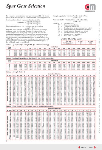
This section outlines a step-by-step method to select appropriate spur gears based on center distance and gear ratio requirements. Key steps include:
- Choosing the number of teeth and module (pitch) for each gear.
- Calculating gear ratio (i = Z2 / Z1) and center distance ((Z1 + Z2) × pitch).
- Evaluating gear strength and wear capacities using specific formulas.
- Determining gear set capacity as the minimum of four power values calculated.
- Comparing calculated capacity with required capacity (actual power × service factor).
- Adjusting pitch, face width, or teeth numbers if capacity is insufficient or overly conservative.
Capacity Calculation Formulas
Two main formulas are used to calculate gear capacities:
- Strength capacity (Ps): Ps = (Xb × Sb × Ys × F × N × Z × P²) / 19,100 × 10³ (kW)
- Wear capacity (Pw): Pw = (Xc × Sc × Yz × F × N × Z × P¹·⁸) / 10,000 × 10³ (kW)
Where parameters include face width (F), shaft speed (N), module (P), material stresses (Sb, Sc), speed factors (Xb, Xc), and factors related to gear geometry (Ys, Yz).
Material Stress Values
- Steel gears: Bending stress Sb = 130 N/mm², Surface stress Sc = 9.65 N/mm²
- Cast gears: Bending stress Sb = 52 N/mm², Surface stress Sc = 9.30 N/mm²
Speed and Geometry Factors
Speed factors (Xb for strength, Xc for wear) depend on shaft rpm and daily operating hours, adjusting capacity for operating conditions and expected gear life (~26,000 hours). Strength factor (Ys) varies with gear tooth count, ranging roughly 0.6 to 0.9. Zone factor (Yz) depends on teeth numbers of both gears, increasing from about 1.0 to nearly 7.0 with tooth count.
Standard Spur Gears Specifications
Standard spur gears are available in modules from 1.0 to 6.0, typically manufactured from medium carbon steels. Modules 1.0 and 1.5 are often induction hardened to enhance wear resistance.
Gear Types and Dimensions
- Gears are categorized as type 'A' or 'B' with catalog suffixes.
- Dimensions include number of teeth, pitch diameter, bore diameters (min and max), hub width, outside diameter, and weight.
- Face widths vary by module and gear type, generally from 6 mm up to 80 mm depending on size.
Module and Pitch Details
- Modules covered: 1.0, 1.5, 2.0, 2.5, 3.0, 4.0, 5.0, 6.0
- Pitch diameters and bore sizes increase proportionally with teeth count and module.
Material and Manufacturing Notes
- Medium carbon steels are standard material.
- Induction hardening applied to smaller modules (1.0 and 1.5) for improved durability.
Critical Recommendations and Best Practices
- Always verify gear capacity against required power multiplied by appropriate service factors to ensure reliability.
- Adjust module and face width to optimize strength and wear resistance.
- Use speed and service hour factors to accurately predict gear life and performance.
- Select teeth numbers carefully to meet desired gear ratio and center distance.
- Consult provided tables for precise factors and dimensions to ensure correct gear selection.
Technical Summary of Spur Gears Catalog
The catalog provides detailed specifications for spur gears categorized by module size, listing key parameters for each gear model.
1. Gear Types and Modules
- Modules covered include 2.5, 3.0, 4.0, 5.0, and 6.0.
- Each module category contains gears with varying teeth counts and pitch diameters.
2. Key Specifications per Gear
- Catalog Number: Unique identifier for ordering.
- Number of Teeth: Influences gear ratio and size.
- Pitch Diameter (dp): Critical for gear meshing compatibility.
- Minimum and Maximum Bore Diameters: Define shaft fitting range.
- Hub Dimension (C): Affects mounting stability.
- Outside Diameter (D): Overall gear size including teeth.
- Weight: Important for mechanical design and balance.
3. Data Organization and Range
Gears are listed in ascending order by teeth count and pitch diameter within each module. Bore sizes and hub dimensions are standardized to facilitate selection.
4. Contact Information
For sales and inquiries:
Telephone: +44 121 360 0155
Fax: +44 121 325 1079
Email: [email protected]
5. Usage Recommendations
Choose gears matching the mechanical system’s module size, appropriate bore size for shaft fitting, and weight constraints. Use catalog numbers for precise ordering and inventory management.
6. Limitations and Notes
Some catalog entries contain incomplete data or placeholders, indicating missing or variable parameters. Users should verify these details with the supplier before finalizing specifications.
Catalog excerpts
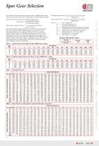
Spur Gear Selection For a required centre distance and gear ratio a suitable pair of spur gears can be selected used and assessed by the following procedure. Select numbers of teeth in gears and module (pitch). Gear Ratio i = Z2 (Teeth driven gear) Z1 (Teeth driven gear) Factors Sb and Sc Gears Gear Type Steel Gears and racks Cast Gears Table 1 Speed factor for Strength Xb (for 26000 hour rating) Daily Hours Table 3 Strength Factor Ys 100 Number of Teeth on Gear being Designed Table 4 Zone Factor Yz (Note: factor same for both gears in gearset) Rack Number of Teeth on Gear being Designed Daily Hours Table 2 Combined Speeed Factor for Wear Xc (for 26000 hour rating) Shaft centre distance in mm = 1 /2 sum gear teeth x pitch = 1 /2 (Z1 + Z2) P From this initial selection each gear can be assessed for strength and wear using the following formulae. The least of the four calculated powers is the capacity of the gear set. The capacity required is determined by multiplying actual power by a service factor relative to driver and driven equipment, refer page c2. If calculated power is below required capacity increase pitch or face width of gears, adjust teeth sizes accordingly, and reassess drive. If calculated power is substantially in excess of required capacity a lower Module could be considered. Strength capacity Ps= Xb x Sb x YS x F x N x Z x P2 kw 19,100 x 103 Wear capacity Pw = Xc x Sc x YZ x F x N x Z x P1.8kw 10,000 x 103 Where:- F = Face width mm N = Gear shaft speed r.p.m. P = Gear pitch, Module No. Sb = Bending stress for gear material (see below) Sc = Surface stress for gear material (see below) Xb = Speed factor for strength - see table 1 Xc = Speed factor for wear - see table 2 YS = Strength factor - see table 3 YZ = Zone factor - see table 4
Open the catalog to page 1
Standard Spur Gears B Dimensions tables for Spur Gears 1.0 and 1.5 Mod. All gears machined from medium carbon, induction hardening steels. Suffix of Cat. No. indicates gear type Gear Widths Pitch Bore Max. Bore No. Teeth Pitch Dia. Min d dp
Open the catalog to page 2
Standard Spur Gears B Dimensions tables for Spur Gears 2.0 to 6.0 Mod. Bore Max. Bore No. Teeth Pitch Dia. Min d dp Suffix of Cat. No. indicates gear type All gears machined from medium carbon steels.
Open the catalog to page 3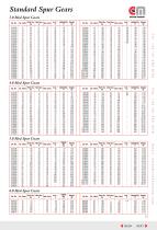
Standard Spur Gears 3.0 Mod Spur Gears Cat. No. Bore Max. Bore No. Teeth Pitch Dia. Min d dp Bore Max. Bore No. Teeth Pitch Dia. Min d dp Bore Max. Bore No. Teeth Pitch Dia. Min d dp
Open the catalog to page 4All Cross & Morse catalogs and technical brochures
 Taper Bushes
2 Pages
 CS Mini Series Couplings
1 Page
 Sheargard Flexible Couplings
2 Pages
 Sheargard Overload Clutches
4 Pages
 PVR Paver Bearings
12 Pages
 Stainless Steel Taper Bushes
2 Pages
 Straight Racks
1 Page
 Bevel and Mitre Gears
6 Pages
 Torque Limiters & Couplings
6 Pages
 KE Couplings
2 Pages
 'L'Series - Jaw Couplings
2 Pages
 Clamping Elements RCK 15
1 Page
 Clamping Elements RCK 13
1 Page
 SC Inverted Tooth Chain
3 Pages
 HV Inverted Tooth Chain
7 Pages
 Roller Chain Catalogue
3 Pages
 Classical Timing Belts
3 Pages
 Clamping Elements RCK 10-12
2 Pages
 'M' Series Sprag Clutches
2 Pages


Archived catalogs
 Gold bearing products
209 Pages
 Transmissions
90 Pages
 Shaft Clamping Elements
28 Pages
 Overload Protection Clutches
4 Pages
 Freewheel Clutches
21 Pages
 Belt & Chain Tensioners
7 Pages
 General Product Catalogue
12 Pages
 Sealmaster Bearings
4 Pages
 Standard Gears
16 Pages
 Shaft Couplings
22 Pages


- Power transmission belt
- Flexible coupling
- Shaft shaft coupling
- Transmission chain
- Flange coupling
- Metal chain
- Torque coupling
- Transfer chain
- Polymer belt
- Transmission coupling
- Rigid coupling
- Timing belt
- Roller chain
- Bearing unit
- Steel chain
- Friction clutch
- Compact coupling
- Sleeve coupling
- Synchronous power transmission belt
- Misalignment correction coupling