
- Catalogs
- CRE TECHNOLOGY
- TECHNICAL DOCUMENTATION GENSYS COMPACT PRIME


- Company
- Products
- Catalogs
- News & Trends
- Exhibitions
TECHNICAL DOCUMENTATION GENSYS COMPACT PRIME

TECHNICAL DOCUMENTATION GENSYS COMPACT PRIME
The GENSYS COMPACT PRIME is a comprehensive controller for synchronizing and paralleling generators in power plants. It supports load sharing and offers electrical/mechanical protections. Available in different mounting versions, it is compatible with the i4Gen touchscreen display and can be configured via multiple interfaces.
The controller manages diesel, gasoline, or gas generators, offering features like preheating, ignition, and start/stop functions. It supports remote start, TEST mode, and J1939 electronic engines, with advanced load sharing and synchronization capabilities.
The front panel includes navigation buttons and an LCD display for menu access and parameter modification. It allows control over generator and mains circuit breakers and mode selection.
Designed for panel mounting, the unit requires static discharge precautions and operates within specific temperature and altitude ranges.
Wiring diagrams must maintain circuit separation unless conductors are rated 600V or greater.
Includes over-voltage category, voltage measurement limits, current input requirements, and communication circuit specifications.
Details on power supply requirements, wiring tools, and conductor protection standards.
Installation requires an enclosure with specific temperature limits.
Features password protection, menu navigation, and event display capabilities.
Emphasizes the use of external fuses, safety practices, and proper cable isolation.
Includes warnings, connection guidelines, input configurations, and protection settings.
Outlines steps for safe generator operation, including breaker management and load checks.
Details on controlling speed and voltage using analog signals or digital outputs.
Explains synchronization conditions and verification steps.
Describes emergency communication protocols for circuit breaker management.
Details on load management post-synchronization.
Explains power regulation using PID controllers.
Describes protection mechanisms for frequency, voltage, current, and reverse power conditions.
Outlines emergency stop procedures and communication error handling.
Details on load sharing settings and static paralleling conditions.
Includes generator excitation parameters and load shedding functions.
Managed via software, with alarms for due maintenance.
Managed via CRE-Link®, with settings for synchronization and power distribution.
Describes manual and auto modes for generator control.
Includes scheduler, alternative selections, and Easy Flex® for custom operations.
Details on Modbus communication capabilities and configuration.
Tracks variable changes with various logging modes.
Network setup and communication protocol details.
Outlines temperature monitoring points for engine performance.
Describes load and torque monitoring for engine efficiency.
Monitors key parameters for engine health.
Details on processing and resetting diagnostic messages.
Guidelines for reliable communication and termination.
Instructions for accessing the module's website and transferring files.
Details on updating firmware via Ethernet.
Lists configurations for various AVR models.
Lists supported parameters for various ECU models.
Details frequency, voltage, current, and reverse power protections with thresholds and timers.
Describes protection mechanisms for unbalance conditions.
Outlines settings for short circuit response.
Details thresholds and actions for earth current faults.
Includes speed, water, oil, and battery protection settings.
Describes protection settings for analog inputs.
Outlines control parameters for circuit breakers.
Details configuration settings for CANopen communication.
Specifies timers for engine operation sequences.
Covers synchronization parameters and control loops.
Describes control loops for power management.
Discusses logging and maintenance settings.
Information on redirecting variables for integration.
Lists inputs and outputs for generator operations.
Catalog excerpts

CRE TECHNOLOGY 130, allee Charles-Victor Naudin Zone des Templiers - SOPHIA ANTIPOLIS 06410 BIOT - FRANCE Phone: + 33 (0)4 .92.38.86.82 www.cretechnology.com [email protected] COPYRIGHT © CRE TECHNOLOGY. ALL RIGHTS RESERVED.
Open the catalog to page 1
TECHNICAL DOCUMENTATION
Open the catalog to page 2
TECHNICAL DOCUMENTATION
Open the catalog to page 3
TECHNICAL DOCUMENTATION Description Presentation GENSYS COMPACT PRIME All-in-one synchronizing and paralleling controller The GENSYS COMPACT PRIME is made for generators used in Power plant applications requiring synchronizing, active and reactive load sharing and electrical/mechanical protections. GENSYS COMPACT PRIME offers flexibility and time saving thanks to its simple wiring, all features included (no option), and easy engineering and programming. Hardware and Display GENSYS COMPACT PRIME is available in both switchboard panel mounted version with display, or core base mounted version....
Open the catalog to page 4
TECHNICAL DOCUMENTATION Control and Management • Complete engine control of diesel, gasoline or gas generators (preheating, pre-glow, ignition, start/stop...). • Alternative or consecutive multiple starter management. • Warm-up and cool down at idle or nominal speed. • Remote start and TEST mode available On/Off load. • Compatible with all J1939 electronic engines. • Isochronous and Iso-voltage active and reactive load sharing. • Fixed KW/KVAR load or Droop mode. • Frequency and voltage control compensation for generators with droop governors and/or AVR/DVR. • Synchronization and dead bus management. •...
Open the catalog to page 5
TECHNICAL DOCUMENTATION
Open the catalog to page 6
(1) Not available according to controller type. Note: Pressing it twice will set the Generator offload and stop the engine without cooling down sequence. Navigation mode Edition mode Scrolling menus. Modifying parameters values once selected: When up/down keys are used to modify values, holding the key will accelerate the entry scrolling. Navigating right/left in display. In MAN mode, when the Generator is offload, use brightness ofthe LCD display. to increase/decrease: ■ The speed when the speed control page is displayed. ■ The voltage when the voltage control page is displayed. Note: Not available...
Open the catalog to page 7
TECHNICAL DOCUMENTATION BUTTON INHIBITION To inhibit front panel buttons, use the CRE Config Software/System/Button inhibition page. This page shows the list of front panel buttons, tick the corresponding box to inhibit actions on the button. Table below shows the 16 bits variable used for remote button inhibition by Modbus, each bit is assigned to a button: external button Requests It is possible to remotely activate button actions by Modbus TCP, for a remote manual control for example. If a button action is controlled by Modbus TCP, the last request received (external or from the front panel)...
Open the catalog to page 8
REAR FACE GENSYS COMPACT PRIME Generator voltage Operating Storage Digital input
Open the catalog to page 9
TECHNICAL DOCUMENTATION The unit is designed for panel mounting, which provdes user with access only to the front panel. WARNING THE UNIT IS NOT GROUNDED • Take all measures against Electronic Static Discharges. • Do not try to open the unit._ Failure to follow these instructions may damage the unit. Environmental requirements: • Operating temperature: -20...70°C (-4...158°F); LCD display slows down a bit under -5°C (23°F). Avoid direct exposure to the sun. • Storage temperature: -40...70°C (-40...158°F). • Altitude: < 4000m (13123ft) for a max AC voltage of 480VAC; < 5000m (16404ft) for a max...
Open the catalog to page 10
TECHNICAL DOCUMENTATION INSTALLATION Preparation • Open type devices to be installed inside a suitable type rated enclosure. • Torque of mounting brackets: 0.4Nm. • Cut out the panel to 220x160mm (8.7x6.3in) minimum. • Make sure the cut-out is smooth and clean.
Open the catalog to page 11
TECHNICAL DOCUMENTATION UL Requirements ADV ANCED WIRING DIAGRAM Circuit separation The communication, sensor, and/or battery derived circuit conductors shall be separated and secured to maintain at least 1/4” (6mm) separation from the Generator and the Bus connected circuit conductors unless all conductors are rated 600V or greater.
Open the catalog to page 12
TECHNICAL DOCUMENTATION MAINS RATINGS Over-voltage Category III, 300VAC system voltage. Sensing Generator / Bus Voltage Measurement (J4) 300VAC max P-N, 2 phases; 500VAC P-P 3 phases, 35...75Hz. Current Inputs (J5) Must be connected through listed or recognized isolating current transformers with secondary rating of 5A max 50/60Hz. (XODW2.8) Instrument transformers (according to IEEE C57.13 series or the equivalent). Communication Circuits Must be connected to communication circuits of UL Listed equipment. Output Pilot Duty (J3) 250VAC, 5A max general purpose, 240VAC, 1/4HP for NO contact, 1/6HP...
Open the catalog to page 13
OTHER CIRCUITS RATINGS
Open the catalog to page 14
TECHNICAL DOCUMENTATION (1> Not available according to controller type. OVERCURRENT PROTECTION (DC SUPPLY AND L1, L2, L3, N) Installer shall protect DC supply and L1, L2, L3, N by fuse Type: R/C (JDYX2/7), or R/C (JDYX2) and CSA Certified Class 1422-30. Rating of fuses: • DC supply to be protected by 5A, 40VDC max. • L1, L2, L3, N, fuse protection 100mA/600VAC max. TERmINALS WIRINg Terminal (screw type): • Tightening Torque: 3.5lb.in (0.4Nm). Wires : • 28-14 AWG, Cu, 75°C min. Conductor protection must be provided in accordance with NFPA 70, Article 240. Low voltage circuits (35VDC or less)...
Open the catalog to page 16
INSTALLATION Preparation • Open type devices to be installed inside a suitable type rated enclosure. • Torque of mounting brackets: 0.4Nm. • Cut out the panel to 220x160mm minimum (8.7x6.3in). • Make sure the cut-out is smooth and clean.
Open the catalog to page 17
TECHNICAL DOCUMENTATION PASSWORD ADVICE The menus will be automatically locked if no operation is performed during the time set in the System menu (Factory setting: 5 minutes). The standby screen will be displayed. The module provides secured password access to protect configuration changes and limit data accessibility: Passwords can be changed via CRE PC software: CRE Config Software To access the Display menu, press To access the Configuration and System menus, the padlock must be released: to select Configuration or System. 2. Press LaSUaH to switch to password input mode (as for other settings);...
Open the catalog to page 18All CRE TECHNOLOGY catalogs and technical brochures
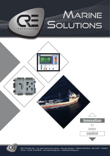 Marine Solutions 2025
4 Pages
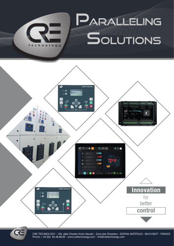 Paralleling
6 Pages
 Generator control
4 Pages
 Hybrid range
6 Pages
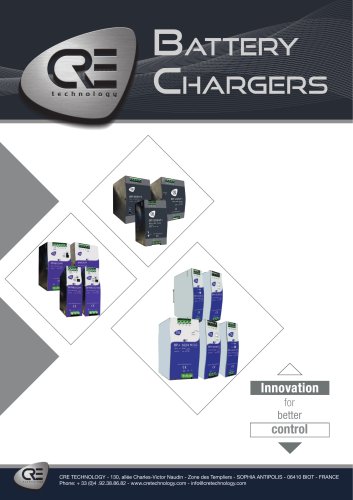 Battery Chargers 2025
4 Pages
Archived catalogs
 DC/DC Converters
2 Pages
 I4GEN suite
2 Pages
 I4GEN.10
2 Pages
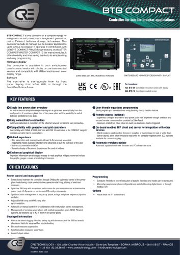 BTB COMPACT
4 Pages
 SCR 2.0
2 Pages
 gensys 2.0 range
4 Pages
 SCR2.0 SALES DOCUMENTATION
2 Pages
 BSD 2.0 SALES DOCUMENTATION
2 Pages
 MARINE SOLUTIONS
4 Pages
 BATTERY CHARGERS
4 Pages
 TRAININGS SESSIONS
4 Pages
 i4GEN
i4GEN2 Pages
 BP range
2 Pages
 GENSYS 2.0 CORE
4 Pages
 product applications
4 Pages
 C2S
C2S16 Pages
 Battery chargers
24 Pages
 ICGEN2.0
55 Pages
 mda-sales-documentation-uk
2 Pages
 GENERATOR CONTROL SOLUTIONS
4 Pages
 avrcompact
2 Pages
 c2s sales documentation
2 Pages
 c2s technical documentation
16 Pages
 paralleling range en c2020
6 Pages
 battery-chargers-range-technical
24 Pages
 Synchro Compact
144 Pages
 COMPACT RANGE
4 Pages


- Electrical cable
- Ethernet switch
- Industrial network switch
- CRE TECHNOLOGY digital I/O
- Power cable
- Junction block
- IO module
- Gigabit Ethernet ethernet switch
- Analog I/O
- Electrical data cable
- RJ45 network switch
- Digital IO module
- DIN rail mounted network switch
- Waterproof network switch
- DC-DC converter
- CRE TECHNOLOGY battery charger
- Unmanaged switch
- Industrial cable
- HMI
- Fieldbus I/O module