- Catalogs
- CRE TECHNOLOGY
- SCR 2.0
- Company
- Products
- Catalogs
- News & Trends
- Exhibitions
SCR 2.0
1 /2Pages

SCR 2.0
1 /2Pages
Catalog excerpts

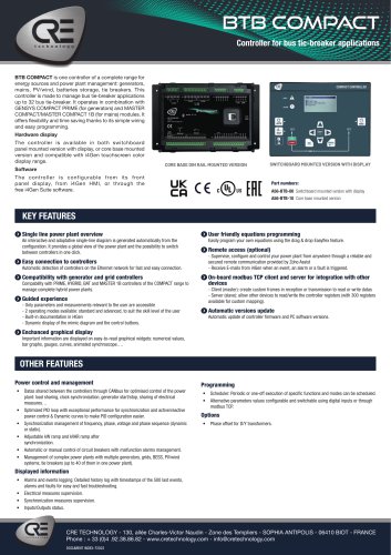
scr 2.0 Synchroscope/Synch check relay SCR 2.0 is a microprocessor controlled synchroscope with programmable synch check relay in a DIN96 front panel mounted package. It monitors the voltage and frequency of 2 independent power sources as well as the instantaneous phase angle between them. The measured parameters are displayed on the 3 digit display and the 24 led circular synchroscope displays the phase angle between the 2 power source. The synchroscope display is only activated if both power source voltages are within the set limits. Synch check relay Front panel configurable 50/60 Hz comptability Basic unit SCR 2.0 MODULE FRONT VIEW SCR 2.0 MODULE REAR VIEW Part numbers: A60X2 SCR 2.0 Module FEATURES & SPECIFICATIONS A SIMPLE PRODUCT FOR SAFETY FUNCTIONS RELAY OUTPUTS Synchronization checking is enabled either via the SYNCH CHECK ENABLE signal input or by pressing the front panel SYNCH pushbutton. If all the necessary conditions are satisfied: The unit provides a synch check relay output with voltage free contacts. • Busbar phase (busbar phase voltage) voltage between set limits. • Generator phase voltage between set limits. • Busbar-generator frequency difference below the set limit. • Busbar-generator voltage difference below the set limit. • Busbar-generator phase difference (phase difference below) below the set limit. The SYNCH CHECK relay will be energized. If the busbar is not powered up, the synch checking may be overridden with the DEAD BUS ENABLE signal input. FRONT PANEL CONFIGURATION SCR2.0 provides a comprehensive set of digitally adjustable threshold and timers. All settings are modified via front panel pushbuttons, and do not require an external unit. The MENU pushbutton allows the digital display to navigate between various measured parameters. The front panel is IP65 for the front panel, IP30 for the rear. RELIABLE AND SIMPLE SCR2.0 is dedicated to basic applications which require no extra costs or expensive hardware. All CRE TECHNOLOGY products aim to provide the same satisfaction levels. The SCR2.0 has passed EMC and low voltage tests, and each unit is 100% tested before delivery. FEATURES 24 led circular synchroscope, programmable ∆V, ∆f, ∆u for check synch relay, 1 phase genset & busbar voltage input, auto power off, adjustable parameters, lug-in connection system for easy replacement. • Maximum humidity: 95% non-condensing. • Case: High Temperature ABS (UL94-V0, 100°C) DIRECTIVES • Low voltage • EU Directives: 2006/95/EC (LVD), 2004/108/EC (EMC) • Normes of reference: EN61010 (safety)/EN61326 (EMC)) CURRENT, VOLTAGE AND FREQUENCY • • • • • • • • Generator voltage: 300 VAC max. (Ph-N) Generator frequency: 0-100 Hz. Busbar voltage: 300 VAC max. (Ph-N) Busbar frequency: 50/60 Hz. Digital inputs: 0 - 30 VDC. DC supply range: 9.0 to 33.0 VDC. Current consumption: 100 mA-DC. Max. operating current: 150 mA-DC (Relay outputs open) • Synch check relay output: 16A/250VAC Dimensions: 102x102x57mm (WxHxD) Panel cut-out dimensions: 92x92mm minimum Weight: 170 g (approx.) Installation: Flush mounted with retaining plastic brackets ENVIRONMENT & PROTECTIONS • Operating temperature: -20°C (-4°F) to 70 °C (158°F). • Storage temperature: -30°C (-22°F) to 80 °C (176°F). CRE TECHNOLOGY - 130, allée Charles-Victor Naudin - Zone des Templiers - SOPHIA ANTIPOLIS - 06410 BIOT - FRANCE Phone : + 33 (0)4 .92.38.86.82
Open the catalog to page 1
scr 2.0 Synchroscope/Synch check relay APPLICATIONS The SCR 2.0 unit works in High-Voltage/Low-Voltage applications where it will test the phase-to-phase synchronization in 100V (rather than phase-neutral). Adjust parameters accordingly. RELATED PRODUCTS The GENSYS COMPACT PRIME CORE is made for gensets used in power plant applications requiring synchronizing, active and reactive load sharing and electrical/mechanical protections. GENSYS COMPACT PRIME CORE offers fl exibility and time saving thanks to its simple wiring, all features included (no option), and easy engineering & programming. The...
Open the catalog to page 2All CRE TECHNOLOGY catalogs and technical brochures
 Marine Solutions 2025
4 Pages
 Paralleling
6 Pages
 Generator control
4 Pages
 Hybrid range
6 Pages
 Battery Chargers 2025
4 Pages
Archived catalogs
 DC/DC Converters
2 Pages
 I4GEN suite
2 Pages
 I4GEN.10
2 Pages
 BTB COMPACT
4 Pages
 gensys 2.0 range
4 Pages
 SCR2.0 SALES DOCUMENTATION
2 Pages
 BSD 2.0 SALES DOCUMENTATION
2 Pages
 MARINE SOLUTIONS
4 Pages
 BATTERY CHARGERS
4 Pages
 TRAININGS SESSIONS
4 Pages
 i4GEN
i4GEN2 Pages
 BP range
2 Pages
 GENSYS 2.0 CORE
4 Pages
 product applications
4 Pages
 C2S
C2S16 Pages
 Battery chargers
24 Pages
 ICGEN2.0
55 Pages
 mda-sales-documentation-uk
2 Pages
 GENERATOR CONTROL SOLUTIONS
4 Pages
 avrcompact
2 Pages
 c2s sales documentation
2 Pages
 c2s technical documentation
16 Pages
 paralleling range en c2020
6 Pages
 battery-chargers-range-technical
24 Pages
 Synchro Compact
144 Pages
 COMPACT RANGE
4 Pages


- Electrical cable
- Ethernet switch
- Industrial network switch
- Digital I/O
- Power cable
- IO module
- Gigabit ethernet switch
- Junction block
- DIN rail mounted network switch
- Analog I/O
- RJ45 network switch
- Waterproof network switch
- Electrical data cable
- Digital IO module
- Unmanaged switch
- Battery charger
- DC-DC converter
- Industrial cable
- HMI
- Fieldbus I/O module