
- Catalogs
- CRE TECHNOLOGY
- ICGEN2.0


- Company
- Products
- Catalogs
- News & Trends
- Exhibitions
ICGEN2.0

ICGEN2.0
The general setup is divided into four submenus: Display setup, Clock setup, Test setup, and Security setup, each allowing specific configurations.
Display Setup
Users can configure screen parameters such as language (default is English), backlight timeout, reset statistics, display contrast, cyclic alarms, alarm off delay, return to default screen time, startup screen, and reset mode at startup.
Clock Setup
This section allows users to set and confirm the date and time, including year, month, day, day of the week, hours, and minutes, with current settings displayed for verification.
Test Setup
Enables or disables automatic tests, sets the type of test (daily, weekly, monthly), and configures the day and time for tests. Parameters include test length, test with load, remote stop settings, and programmable test options.
Security Setup
Allows users to enter access codes to lock or unlock programming menus. Default codes are provided for mains, genset, engine, special functions, connectivity, I/O, and state passwords. A global code can be set for accessing programming menus.
Alarms List
Divided into Mains alarms, Generator alarms, Engine alarms, and General alarms. Users can configure alarms by setting parameters such as activation, delay, retentive status, action, siren activation, SMS notifications, and global alarm outputs.
Alarms Default Parameters
Includes a detailed list of default parameters for each alarm, such as alarm code, name, activation conditions, delay, retentive status, action type, and additional outputs like siren and SMS notifications.
- Mains Alarms: Include low/high frequency and voltage, V asymmetry, and faulty mains indicators.
- Generator Alarms: Cover low/high frequency and voltage, phase sequence issues, short circuit, overload, and V asymmetry.
- Other Alarms: Include ground protection, emergency stop, user alarms, protection trip, and various engine-related alarms such as start failure, mechanical faults, temperature, fuel, oil pressure, and battery voltage issues.
- SCR: Allows generator start via remote signal, with configurable delay times and switch settings.
- Start by Mains kW: Automates generator start/stop based on mains consumption thresholds.
- Dummy Load: Activates outputs based on load consumption thresholds.
- Input/Output Setup: Configures digital input/output functions and types, including normally open/closed settings.
- Measures: Adjusts voltage and current settings.
Catalog excerpts

Instructions Manual CRE TECHNOLOGY believes that all information provided herein is correct and reliable and reserves the right to update at anytime. CRE TECHNOLOGY does not assume any responsibility for
Open the catalog to page 1
1. GENERAL REQUIREMENT & INSTALLATION 1.1 General notes WARNING! • Carefully read the manual before the installation or use. • This equipment is to be installed by qualified personnel, complying to current standards, to avoid damages or safety hazards. • Before any maintenance operation on the device, remove all the voltages from measuring and supply inputs and short‐circuit the CT input terminals. • Products illustrated herein are subject to alteration and changes without prior notice. • Technical data and descriptions in the documentation are accurate, to the best of our knowledge, but no liabilities...
Open the catalog to page 4
Hardware settings GENERAL CHARACTERISTICS Rated voltage Vdc Allowed Vdc Rated voltage Vac Allowed Vac Allowed frequency Max consumption with backlight Temperature range DISPLAY DIGITAL INPUTS N° STATIC OUTPUT N° SERIAL COMMUNICATION INTERFACE Interface type Cable length Baud rate Interface type Baud rate CONTACTORS RELAYS N°outputs Type of contacts Contatcs capacity LOAD CURRENTS INPUT N° Measure range Precision VOLTAGE INPUTS N° Input type Rated voltage Measure range Precision ACTIVE POWER MEASURE Measure type Precision 12Vdc (24Vdc) from 6Vdc to 33Vdc 400 Vac Up to 500 Vac From 45 to 75 Hz...
Open the catalog to page 5
Electrical installations Warning! before inserting the plugs make sure that the connections strictly comply with the wiring diagram below. For more informations about programmable inputs/outputs, see par. 2‐1O. WARNING: All these terminals are not used for
Open the catalog to page 6
J1 – Genset AC voltage and contactors 1.1 – Not used 1.2 – Not used 1.3 – Not used 1.4 – Not used 1.5 ‐ Genset voltage phase 1 1.6 ‐ Genset voltage phase 2 1.7 ‐ Genset voltage phase 3 1.8 ‐ Neutral J3 – Genset AC current 3.1 ‐ Genset current I1 3.2 ‐ Genset current I2 3.3 ‐ Genset current I3 3.4 CT common J9 – Digital Inputs 4.1 ‐ Gnd 4.2 ‐ Gnd 4.3 ‐ Gnd 4.4 – Programmable digital input (default ‐ Low coolant level) 4.5 – Programmable digital input (default – High engine temperature D) 4.6 – Programmable digital input (default – Remote start) 4.7 – Programmable digital input (default – Remote...
Open the catalog to page 7
J1 – Genset AC voltage and contactors 1.1 ‐ Mains contactor output (NC) 1.2 ‐ Mains contactor output (NC) 1.3 ‐ Genset contactor output (NO) 1.4 ‐ Genset contactor output (NO) 1.5 ‐ Genset voltage phase 1 1.6 ‐ Genset voltage phase 2 1.7 ‐ Genset voltage phase 3 1.8 ‐ Neutral J2 – Mains AC voltage 2.1 ‐ Mains voltage phase 1 2.2 ‐ Mains voltage phase 2 2.3 ‐ Mains voltage phase 3 2.4 ‐ Neutral 3.1 ‐ Genset current I1 3.2 ‐ Genset current I2 3.3 ‐ Genset current I3 3.4 – CT common J5 – Supply and Outputs 5.1 ‐ Battery negative 5.2 ‐ Battery positive 5.3 ‐ Common positive for the relay outputs...
Open the catalog to page 8
TCGEN2.0 J1 - Genset AC voltage and contactors 1.1 - Mains contactor output (NC) 1.2 - Mains contactor output (NC) 1.3 - Genset contactor output (NO) 1.4 - Genset contactor output (NO) 1.5 - Genset voltage phase 1 1.6 - Genset voltage phase 2 1.7 - Genset voltage phase 3 1.8 - Neutral J2 - Mains AC voltage 2.1 - Mains voltage phase 1 2.2 - Mains voltage phase 2 2.3 - Mains voltage phase 3 2.4 - Neutral J3 - Genset AC current 3.1 - Genset current I1 3.2 - Genset current I2 3.3 - Genset current I3 3.4 - CT common J5 - Supply and Outputs 5.1 - Battery negative 5.2 - Battery positive 5.3 - Common...
Open the catalog to page 9
Operation mode Automatic mode ACGEN2.0: The engine automatically starts in case of remote start input or test activation (with automatic management of KG, if one output is programmed as KG ON), the engine is stopped when the remote start is removed or at the end of the test procedure. During the starting phase it is possible to stop the engine with the STOP button. At the end of this phase the button is disabled. Use the RESET button to stop the engine. Push the AUT button to select this functioning mode. ICGEN2.0: Push the AUT button to select this functioning mode. In case of mains failure...
Open the catalog to page 10
Reset mode ACGEN2.0: The engine cannot work. If you select Reset mode, the alarms are reset and the engine stops immediately if it is working. If the cause of the alarm remains, it is not possible reset the alarm. Push the RESET button to select this functioning mode. ICGEN2.0: The remote start output cannot be activated. If the mains is available it is connected to the load. If you select Reset mode, the alarms are reset and the remote start output is deactivated. If the cause of the alarm remains, the cause is still present. Push the RESET button to select this functioning mode. TCGEN2.0: The...
Open the catalog to page 11
Cngtn* Conir«i
Open the catalog to page 12
Display pages Navigation diagram When you turn on the board, you will see the logo page. Then you will be in the stand‐by page with engine OFF (Mains 1). When you start the generator, you will go in the starting page, that will disappear when the start is completed, and redirects you to the running page. When you stop the engine, you will see a stopping page, then you will return automatically to the page you were in when you pressed the stop button. With the left and right arrows, you can move through the different sections, and with the up and down arrows you can scroll the pages of the selected...
Open the catalog to page 15
Display pages – Navigation cursors The cursors on the upper side and left side of the display indicate the position of the page inside the navigation diagram: the left and right arrows move the page along with horizontal cursor. The left arrow button allows to return back to the previous section: in this case from the generator pages to the mains pages. If the vertical cursor is available on display it’s possible to use up and down arrow buttons to see more pages for the section: in this case from the mains measure #1 to mains measure #2. With up arrow button you can return to the previous page...
Open the catalog to page 16All CRE TECHNOLOGY catalogs and technical brochures
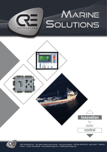 Marine Solutions 2025
4 Pages
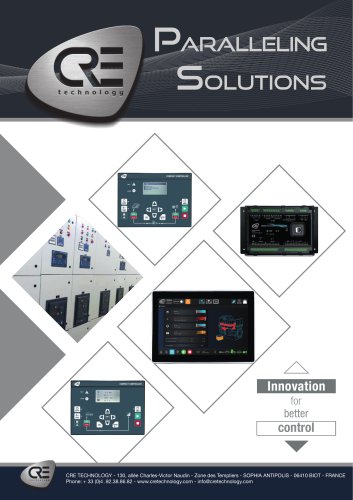 Paralleling
6 Pages
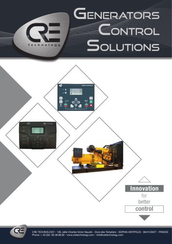 Generator control
4 Pages
 Hybrid range
6 Pages
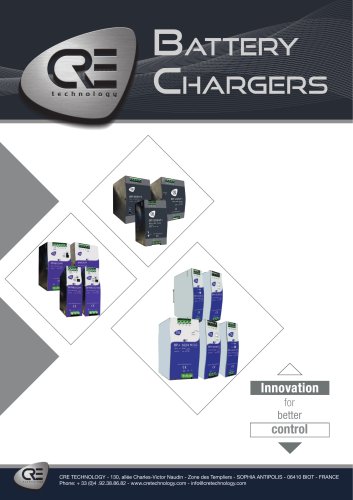 Battery Chargers 2025
4 Pages
Archived catalogs
 DC/DC Converters
2 Pages
 I4GEN suite
2 Pages
 I4GEN.10
2 Pages
 BTB COMPACT
4 Pages
 SCR 2.0
2 Pages
 gensys 2.0 range
4 Pages
 SCR2.0 SALES DOCUMENTATION
2 Pages
 BSD 2.0 SALES DOCUMENTATION
2 Pages
 MARINE SOLUTIONS
4 Pages
 BATTERY CHARGERS
4 Pages
 TRAININGS SESSIONS
4 Pages
 i4GEN
i4GEN2 Pages
 BP range
2 Pages
 GENSYS 2.0 CORE
4 Pages
 product applications
4 Pages
 C2S
C2S16 Pages
 Battery chargers
24 Pages
 mda-sales-documentation-uk
2 Pages
 GENERATOR CONTROL SOLUTIONS
4 Pages
 avrcompact
2 Pages
 c2s sales documentation
2 Pages
 c2s technical documentation
16 Pages
 paralleling range en c2020
6 Pages
 battery-chargers-range-technical
24 Pages
 Synchro Compact
144 Pages
 COMPACT RANGE
4 Pages


- Electrical cable
- Ethernet switch
- Industrial network switch
- CRE TECHNOLOGY digital I/O
- Power cable
- Junction block
- IO module
- Gigabit Ethernet ethernet switch
- Analog I/O
- Electrical data cable
- RJ45 network switch
- Digital IO module
- DIN rail mounted network switch
- Waterproof network switch
- DC-DC converter
- CRE TECHNOLOGY battery charger
- Unmanaged switch
- Industrial cable
- HMI
- Fieldbus I/O module