- Catalogs
- CRE TECHNOLOGY
- c2s technical documentation
- Company
- Products
- Catalogs
- News & Trends
- Exhibitions
c2s technical documentation
1 /16Pages

c2s technical documentation
1 /16Pages
Catalog excerpts

C2S “Synchronization and safety column” Technical documentation Part number : A25 Z0 9 0004 G-EN Last update : January 2016 CRE Technology believes that all information provided herein is correct and reliable and reserves the right to update at any time. CRE Technology does not assume any responsibility for its use. E & O E.
Open the catalog to page 1
1. CRE Technology 130 Allée Charles-Victor Naudin Zone des Templiers – Sophia Antipolis 06410 – BIOT FRANCE Phone: +33 492 38 86 82 Fax: +33 492 38 86 83 Website: http://www.cretechnology.com Email: [email protected] All CRE Technology products are delivered with one year warranty, and if necessary we will be happy to come on site for product commissioning or troubleshooting. The company also provide specific trainings on our products and softwares. Technical support: +33 492 38 86 86 (8H30-12H00 / 14H00-18H00 GMT+1) Email: [email protected] SKYPE: support-cretechnology.com Read...
Open the catalog to page 2
C2S - CRE Technology - Official Technical documentation
Open the catalog to page 3
C2S – CRE Technology – Official Technical documentati
Open the catalog to page 4
2. Introduction This second generation microprocessor module, created by C.R.E., is a module for manual coupling which integrates a synchronisation column and the syncheck authorisation relay. The synchronisation column allows visualisation of phase, frequency and voltage difference between one or several gensets to be coupled to a bus bar or reference bus. The authorisation relay allows safe coupling only when the conditions meet the requirements of the installation. This new version of C2S features the following functions: CE mark conformity, thanks to a new electronic and mechanical...
Open the catalog to page 5
Putting into service The Synchronisation and Safety Column (C2S) is powered by the generator voltage on Vgen terminals 4 and 5. WARNING : The module C2S is powered from 60% of nominal generator voltage value, and up to 115% as a maximum. Not damage the C2S, Voltage must not exceed 115%. 3.2 Auto/Manual Mode The bargraphs and signalling of the C2S module function as follows: In manual mode (terminals 6-7 open), all the displays and functions are in order. The "AUTO" LED is not lit. In automatic mode (terminals 6-7 closed), the synchronoscope and the 2 differential bargraphs (voltmeter and...
Open the catalog to page 6
3.4 Micro-shunts The micro-shunt JP1 configures the C2S to authorise the closure of the output relay when no voltage is present on the bus and the generator voltage is correct (between 85% and 115% of the nominal value). The JP2 micro-shunt allows a self-test of all the module's LEDs when the system is powered up. Chapitre : Operation WARNING : The LEDs test lasts approximately 8 seconds. C2S – CRE Technology – Official Technical documentation
Open the catalog to page 7
4. Configuration - Factory settings To access potentiometers and micro-shunts, it is necessary to remove the back cover of the module. WARNING : Check that no voltage is present on the terminal trip before removing the cover. Note : The RV1 potentiometer is factory configured and should not be altered. - RV2 "phase difference" Potentiometer: This potentiometer enables the adjustment of the allowed phase difference between +/-5° (fully counter-clockwise) and +/-20° (fully clockwise). Factory setting 10°. - RV3 "voltage difference" Potentiometer: This potentiometer enables the adjustment of the...
Open the catalog to page 8
5. Putting into service – Control - Disconnect the wires from the coupling authorisation relay's isolated contact (terminals 8-9), so as to prevent the coupling of the generator with the bus. - Feed the C2S module with generator voltage Vgen, on terminals 4 and 5. Generator voltage to be coupled and the bus voltage should both be present. - Check the relationship between the phases applied in VGEN (terminals 4-5) and VBUS (terminals 2-3) on the C2S 2 opposite phases generate a 180° coupling. Different phases on VGEN and VBUS generate a +/-120° coupling. - Check that the voltage presence LEDs...
Open the catalog to page 9
6. EMC precaution - CE mark conformity The C2S version A25Zx is conformed to European CE mark requirements. Here below some tips to use the C2S. - Faraday cage effect: The C2S is painted with a conductive paint. We recommend maintaining surface contact between the C2S casing and the switchboard housing. If the back cover needs to be removed, replace it and screws must be fully tightened. Chapitre : EMC precaution - CE mark conformity For IP65 protection use a gasket (preferably conductive to ensure EMC). For more details about the positioning and the dimensions (in mm) of the gasket, refer to...
Open the catalog to page 10
WARNING : Check carefully that the phases connected on the generator voltage are the same as those connected on the reference bus voltage and in the same order. Remember that 2 opposite phases generate a 180° coupling and that different phases on the generator voltage and the bus voltage generate a +/-120° coupling. C2S – CRE Technology – Official Technical documentation Chapitre : WIring Diagram The voltage VGEN of the generator to be coupled is connected by 2 wires on terminals 1 and 2. The voltage VBUS of the reference bus is connected by 2 wires on terminals 3 and 4. If the supplying voltages...
Open the catalog to page 11
❖ Alternative input voltages: • Generator measuring voltage (VGEN) and power supply: 50 and 60 Hz (maximum consumption <4VA). Cutting power: 2000VA resistive load Nominal voltage /Maximal cutting voltage 250VCA/440VCA Nominal cutting current 8A WARNING : Differential voltage bargraph is flashing when one or both of the voltage is out of ranges above and not at zero. C2S - CRE Technology - Official Technical document
Open the catalog to page 12
Chapitre : Size C2S – CRE Technology – Official Technical documentation
Open the catalog to page 13
Chapitre : Mounting C2S – CRE Technology – Official Technical documentation
Open the catalog to page 14
11. CRE TECHNOLOGY, WHERE TO FIND US 130 Allee Charles-Victor Naudin Zone des Templiers - Sophia Antipolis 06410 - BIOT FRANCE Phone: +33 492 38 86 82 Fax: +33 492 38 86 83 Website: http://www.cretechnology.com Email: [email protected] PARC FORESTIER DEPARTMENTAL DE IA BRAGUE s VERS VALBONNE Chapitre : CRE TECHNOLOGY, where to find us PARC FORESTIER D&ARTEMENTAL DE LA VAIA^ASQUE SCHEMA DES ACCfeS ACCES n° 20- Allee Victor Naudin C2S - CRE Technology - Official Technical documentation
Open the catalog to page 15All CRE TECHNOLOGY catalogs and technical brochures
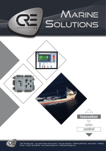 Marine Solutions 2025
4 Pages
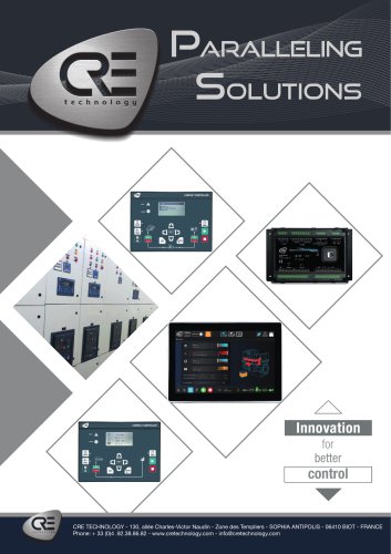 Paralleling
6 Pages
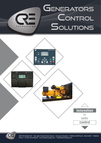 Generator control
4 Pages
 Hybrid range
6 Pages
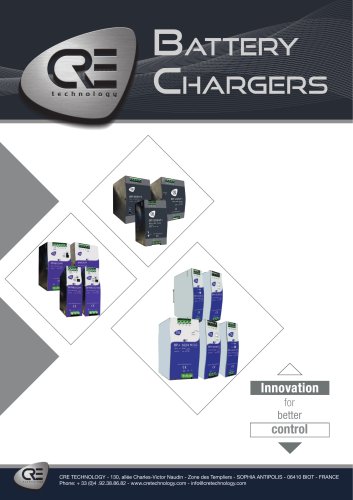 Battery Chargers 2025
4 Pages
Archived catalogs
 DC/DC Converters
2 Pages
 I4GEN suite
2 Pages
 I4GEN.10
2 Pages
 BTB COMPACT
4 Pages
 SCR 2.0
2 Pages
 gensys 2.0 range
4 Pages
 SCR2.0 SALES DOCUMENTATION
2 Pages
 BSD 2.0 SALES DOCUMENTATION
2 Pages
 MARINE SOLUTIONS
4 Pages
 BATTERY CHARGERS
4 Pages
 TRAININGS SESSIONS
4 Pages
 i4GEN
i4GEN2 Pages
 BP range
2 Pages
 GENSYS 2.0 CORE
4 Pages
 product applications
4 Pages
 C2S
C2S16 Pages
 Battery chargers
24 Pages
 ICGEN2.0
55 Pages
 mda-sales-documentation-uk
2 Pages
 GENERATOR CONTROL SOLUTIONS
4 Pages
 avrcompact
2 Pages
 c2s sales documentation
2 Pages
 paralleling range en c2020
6 Pages
 battery-chargers-range-technical
24 Pages
 Synchro Compact
144 Pages
 COMPACT RANGE
4 Pages


- Electrical cable
- Ethernet switch
- Industrial network switch
- CRE TECHNOLOGY digital I/O
- Power cable
- Junction block
- IO module
- Gigabit ethernet switch
- DIN rail mounted network switch
- Analog I/O
- RJ45 network switch
- Waterproof network switch
- Electrical data cable
- Digital IO module
- Unmanaged switch
- CRE TECHNOLOGY battery charger
- DC-DC converter
- Industrial cable
- Fieldbus I/O module
- HMI