- Catalogs
- CRE TECHNOLOGY
- c2s sales documentation
- Company
- Products
- Catalogs
- News & Trends
- Exhibitions
c2s sales documentation
1 /2Pages

c2s sales documentation
1 /2Pages
Catalog excerpts

C2SAuto synchronizer and safety column• Led synchronoscope • Protections • Manual and Automatic modes This second generation of microprocessor module combines all the visualization and control functions needed to couple a generator to a bus bar manually: display of the phase, frequency and voltage differences, a safety relay which monitors these three parameters and indicates the status of the installation. This new version does not need an external DC power supply, as it takes it from the busbar. The reduced size allows the use of DIN92 format tools and its heavy duty metal case can operate in extreme environment. SYNCHRONIZATION COLUMN Led synchroscope: 18 LEDs spread over 360° display the phase difference. The synchroscope lines up when the frequency difference is less than 0.5 Hz. Differential frequency meter: The frequency difference is displayed by a 17 LED bar graph corresponding to ± 5 Hz with an expanded scale over 1 Hz. Differential voltmeter: The voltage difference is displayed by a 17 LED bar graph corresponding to ± 20%. SAFETY RELAY The coupling authorization relay monitors the difference in frequency, voltage and phase. It authorizes coupling only when all the parameters meet the requirements of the installation. Frequency difference: Coupling authorization is given for a frequency difference of less than 0.1 Hz. Phase difference: The phase difference which authorizes coupling is adjustable between ± 5° and ± 20°. Voltage difference: The voltage difference which authorizes coupling is adjustable between ± 2.5% and ± 20%.
Open the catalog to page 1
LED INFORMATION Presence of generator voltage (Vgen): Shows that the voltage of the generator or the power source to be coupled is between 85% and 115% of its nominal value. Presence of bus voltage (Vbus): Shows that the voltage of the bus to which the generator must be coupled is between 85% and 115% of its nominal value. Voltage difference fault (AV): Shows that the voltage difference between the generator and the bus is greater than the safety relay setting. Coupling in automatic mode (Auto): Shows that the installation is in automatic coupling mode. The synchronization column is active but...
Open the catalog to page 2All CRE TECHNOLOGY catalogs and technical brochures
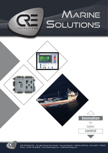 Marine Solutions 2025
4 Pages
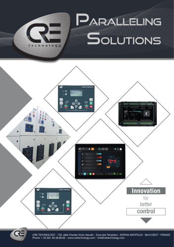 Paralleling
6 Pages
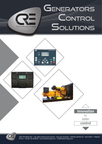 Generator control
4 Pages
 Hybrid range
6 Pages
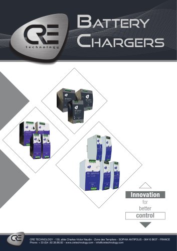 Battery Chargers 2025
4 Pages
Archived catalogs
 DC/DC Converters
2 Pages
 I4GEN suite
2 Pages
 I4GEN.10
2 Pages
 BTB COMPACT
4 Pages
 SCR 2.0
2 Pages
 gensys 2.0 range
4 Pages
 SCR2.0 SALES DOCUMENTATION
2 Pages
 BSD 2.0 SALES DOCUMENTATION
2 Pages
 MARINE SOLUTIONS
4 Pages
 BATTERY CHARGERS
4 Pages
 TRAININGS SESSIONS
4 Pages
 i4GEN
i4GEN2 Pages
 BP range
2 Pages
 GENSYS 2.0 CORE
4 Pages
 product applications
4 Pages
 C2S
C2S16 Pages
 Battery chargers
24 Pages
 ICGEN2.0
55 Pages
 mda-sales-documentation-uk
2 Pages
 GENERATOR CONTROL SOLUTIONS
4 Pages
 avrcompact
2 Pages
 c2s technical documentation
16 Pages
 paralleling range en c2020
6 Pages
 battery-chargers-range-technical
24 Pages
 Synchro Compact
144 Pages
 COMPACT RANGE
4 Pages


- Electrical cable
- Ethernet switch
- Industrial network switch
- CRE TECHNOLOGY digital I/O
- Power cable
- Junction block
- IO module
- Gigabit ethernet switch
- DIN rail mounted network switch
- Analog I/O
- RJ45 network switch
- Waterproof network switch
- Electrical data cable
- Digital IO module
- Unmanaged switch
- CRE TECHNOLOGY battery charger
- DC-DC converter
- Industrial cable
- Fieldbus I/O module
- HMI