- Catalogs
- CRE TECHNOLOGY
- battery-chargers-range-technical
- Company
- Products
- Catalogs
- News & Trends
- Exhibitions
battery-chargers-range-technical
1 /24Pages

battery-chargers-range-technical
1 /24Pages
Catalog excerpts

technica l addend um www.creiec
Open the catalog to page 3
Technica l addend um www.crejechnolocy.com
Open the catalog to page 5
Technical addendum This document is intended to help understand our Product information and technical documentations, and make informed choices. It starts with installation hints. COMMON FEATURES Mounting Only install the charger in a pollution degree 2 environment (dry, well‐ventilated locations). Hang the charger vertically with the input terminal strip at the bottom. To fasten the charger on the 35 DIN rail (7.5 or 15): 1. Tilt the charger slightly rearwards 2. Fit the charger over top hat rail 3. Slide it downward until it hits the stop 4. Press against the bottom for locking 5. Shake the...
Open the catalog to page 6
Technical addendum By design our chargers are category II regarding the installation. As illustrated for home and factory, the risk of electrical shock is higher upstream in the distribution system, especially if the location is lightning-prone: CAT II: all outlets at more than 10m from CAT III or 20m from CAT IV If the category III or IV is required, a surge protection device must be added. Ask our customer service for advice. 1.2 Definitions The individual technical documentations specify various characteristics, such as Charger inrush current: at power-on, a large pulse current is draft...
Open the catalog to page 7
Technica l addend um www.crejechnolocy.com Connect the protective earth to ground. Isolate the charger from the AC source, before connecting or disconnecting a battery. Do not open the charger. Never charge a frozen battery. Due to a charge imbalance risk, avoid charging batteries in parallel. This table is given for information only; check with the battery manufacturer. To function as a "float charger" which senses the reduction in charging current and reduces the charging voltage, implement a boost strategy with a BPR B charger (see BPRB range/Overview); an external logic must remove the boost...
Open the catalog to page 8
Technical addendum Derating The performance might downgrade beyond the specified limits in the technical documentations: AC voltage below lower limit: Example: BP0524M (the AC voltage limit is 85V or 170V depending on the position of a switch) Temperatures above the limits: NOTE General outlines are shown here. To see the accurate curves, refer to the specific Product information.
Open the catalog to page 9
Technical addendum Paralleling chargers For a better availability or to increase the output currents, it is advised to parallelize several chargers. Except for BP+ range (where the diode is built in), Schottky diodes must be installed so that there is no reverse current and harmonics do not add. Redundancy is also possible. The diode SBX 2550 is connected between the terminals of a DIN terminal module. The kit includes the module and the diode. The chargers are hooked up as follows (in this case, AC inputs are L1-N): L1 For an optimal charge: 1. Adjust to identical voltages on both chargers (at...
Open the catalog to page 10
Technica l addend um www.crejechnolocy.com Diagram block: A DC OK isolated relay output is activated in event of any fault. It is an NO contact. 2.1 Protections A Schottky diode must be installed on the output (positive terminal) to prevent reverse power in the case the battery has a higher voltage. It might result from a power outage: then the relay opens, the led goes off (unless there is no diode). The battery higher voltage might also be due to the charge by a charge alternator of a generator. Internal protections: • Overcurrent: constant current limiting. The charger provides constant current...
Open the catalog to page 11
Technica l addend um www.crejechnolocy.com Example of installation (the fuse and fuse module on the right are NOT provided): In this example, the diode is connected to the module on the right, but it can also span across the two smaller modules. AC side: install a fuse or a breaker on the input. The AC currents, and inrush currents in cold start, show in the data sheets. We suggest the following: Make sure that all strands of each stranded wire enter the connection terminal and the screw terminals are securely fixed to prevent poor contact.
Open the catalog to page 12
BPxxxx 9 0020 b en Technical addendum 2.3 Comparison of the various models
Open the catalog to page 13
Technica l addend um www.crejechnolocy.com OVP = Over Voltage Protection OTP = Over Temperature Protection by temperature switch (detection on one or both sides of the transformer) Leakage current: the Y capacitors between I/P and FG cause some leakage current flow from line or neutral to the case; the leakage current to the case is not dangerous. A proper connection to ground discharges the case. 3.1 Protections A Schottky diode must be installed on the output (positive terminal) to prevent reverse power in the case the battery has a higher voltage (due to input outage [the led goes off unless...
Open the catalog to page 14
Technica l addend um www.crejechnolocy.com AC side: insert a breaker or fuse. The AC currents, and inrush currents in cold start, show in the data sheets. We suggest the following: Dual phase input in Wye connection: use of only two phases 3.3 Power factor The power switching generates harmonics and the capacitors do not absorb currents in phase with the source. Use BP1024M or BP2024M when the power factor is a concern: • BP 1024M features an active PFC function; the block diagram is similar to the one of the BPRB range (without UVP, see further). This results in a high power factor. • BP 2024M...
Open the catalog to page 15
Technica l addend um www.crejechnolocy.com * Derating from 55°C @230 Vac, from 40°C @110Vac ** 2 kV for BP 4024T
Open the catalog to page 16
Technica l addend um www.crejechnolocy.com I/P = Input, FG = Front Ground OCP = Over Current Protection OVP = Over Voltage Protection OTP = Over Temperature Protection by temperature switch (sensor in air) Leakage current: the Y capacitors between I/P and FG cause some leakage current flow from line or neutral to the case; the leakage current to the case is not dangerous. A proper connection to ground discharges the case. 4.1 Protections The integral Schottky diode prevents reverse power in the case the battery has a higher voltage (due to input outage [the led goes off], or due to the charge...
Open the catalog to page 17All CRE TECHNOLOGY catalogs and technical brochures
 Marine Solutions 2025
4 Pages
 Paralleling
6 Pages
 Generator control
4 Pages
 Hybrid range
6 Pages
 Battery Chargers 2025
4 Pages
Archived catalogs
 DC/DC Converters
2 Pages
 I4GEN suite
2 Pages
 I4GEN.10
2 Pages
 BTB COMPACT
4 Pages
 SCR 2.0
2 Pages
 gensys 2.0 range
4 Pages
 SCR2.0 SALES DOCUMENTATION
2 Pages
 BSD 2.0 SALES DOCUMENTATION
2 Pages
 MARINE SOLUTIONS
4 Pages
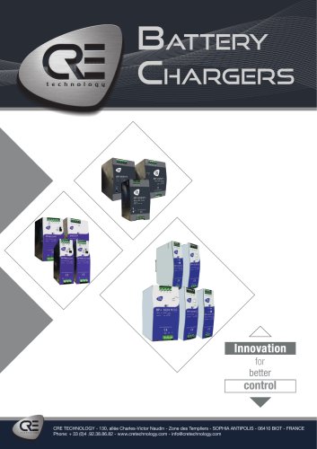
 BATTERY CHARGERS
4 Pages
 TRAININGS SESSIONS
4 Pages
 i4GEN
i4GEN2 Pages
 BP range
2 Pages
 GENSYS 2.0 CORE
4 Pages
 product applications
4 Pages
 C2S
C2S16 Pages
 Battery chargers
24 Pages
 ICGEN2.0
55 Pages
 mda-sales-documentation-uk
2 Pages
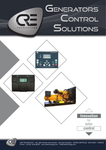
 GENERATOR CONTROL SOLUTIONS
4 Pages
 avrcompact
2 Pages
 c2s sales documentation
2 Pages
 c2s technical documentation
16 Pages
 paralleling range en c2020
6 Pages
 Synchro Compact
144 Pages
 COMPACT RANGE
4 Pages


- Electrical cable
- Ethernet switch
- Industrial network switch
- CRE TECHNOLOGY digital I/O
- Power cable
- Junction block
- IO module
- Gigabit ethernet switch
- DIN rail mounted network switch
- Analog I/O
- RJ45 network switch
- Waterproof network switch
- Electrical data cable
- Digital IO module
- Unmanaged switch
- CRE TECHNOLOGY battery charger
- DC-DC converter
- Industrial cable
- Fieldbus I/O module
- HMI