

LINEAR MOTOR STAGE

LINEAR MOTOR STAGE
The document outlines the technical specifications and features of the CLS, CLMS, and MMLS series of linear motor stages, designed for high precision and velocity with a compact and rigid structure suitable for various thrust requirements.
The CLS series features a base with a stator and a wide-type linear guide for its aluminum slider, incorporating an optical scale for enhanced position feedback. Key features include lightweight design, high velocity and acceleration, smooth motion, and multi-slider control on the same axis. Customization options are available.
Details include module parameters, mounting dimensions, wiring definitions, slider dimensions, and assembly dimensions for CLS series models, with dynamic characteristics illustrated through response charts.
The CLMS series is noted for accuracy and includes models CA2, CA6, CB4, and CC4. Assembly and mounting dimensions are provided, along with standard specifications.
The MMLS series highlights linear motor stage features with specified module parameters and mounting dimensions for CA2 and CA4 models.
Includes ordering information and accessory options, with a selection application table to assist in choosing the appropriate model.
The linear motor stages offer advanced features for high precision and velocity applications, with customization options to meet specific requirements.
The CLMS series direct drive systems enhance productivity and dynamic motion performance, characterized by high precision positioning platforms, high load linear guides, efficient linear motors, and position feedback encoders.
- Dustproof Design: Ensures performance in adverse environments.
- Compact Design: Optimizes space without compromising thrust conditions.
- High Reliability: Horizontal encoder installation prevents external impacts.
- High Velocity and Acceleration: Reaches velocities up to 6m/s and accelerations of 60m/s².
- Customization: Options for optical encoders and various designs.
- Module Parameters: Includes current, force constant, back EMF constant, resistance, inductance, magnetic pole pitch, slider mass, peak current, continuous force, and peak force.
- Mounting Dimensions: Detailed for various models.
- Standard Specifications: Includes total length, effective travel, and module weight.
The CLMS series is ideal for replacing belt and ball screw linear systems due to its ease of use and high performance.
Includes continuous force charts for P-series ironless and C-series ironcore models.
Details specifications and conditions for motion applications such as pick and place, scanning, inspection, and cutting.
- Point-to-Point Motion without Constant Velocity: Covers applications like pick and place with parameters like load mass and velocity.
- Point-to-Point Motion with Constant Velocity: Relevant for scanning and inspection, focusing on constant velocity.
- Specifications for maximum output voltage, continuous current, and peak current.
- Details on resolution and type (analog or digital).
- Considers temperature, vacuum conditions, and clean room levels.
- Focuses on positioning and repetitive accuracy.
- Options include horizontal, vertical, and tilt.
- Includes flat, vertical, and wall mount options.
- Indicates any space restrictions.
Catalog excerpts

Linear motor Stage * cpc reserves the right to revise any information(technical details) any time without notice, for printing mistakes or any other incidental mistakes. We take no responsibility. HEADQUARTERS Chieftek Precision Co., Ltd. No.3, Dali 1st Rd., Xinshi Dist., Southern Taiwan Science Park, Tainan City .741-45, Taiwan (R.O.C) TEL:+88fi-6-505 5858 Http://www.chieftek.com E-mail:[email protected] Chieftek Precision USA 2280 E. Locust Court. Ontario, CA 91761, USA Tel:+1-909-773-1200 Fax:+1-909-773-1202 cpc Europa GmbH industriepark 314, D-78244 Gottmadingen, Germany TEL:+49-7731-59130-38 FAX:+49-7731-59130-28
Open the catalog to page 1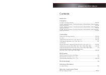
LINEAR MOTOR STAGE Contents Introduction
Open the catalog to page 2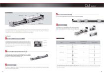
CLS-series Rail Optical scale Block Coil Assembly Compared to traditional ball screw modules, the drive coupled CLS series provides superior precision and velocity under many thrust output conditions. The highly integrated model design also enables a much increased productivity and reliability as compared to the accuracy and speed limitations of traditional ball screw systems. Features impact Structure Multiple slider on same axis CLS can contain multiple sliders on the same axis, each individually controllable. 5 Customization CLS modules can be customized for specific customer applications....
Open the catalog to page 3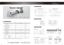
CLS-PM4 Dynamic response chart (300VDC unloaded) Dynamic Characteristics CLS-PM6 Dynamic response chart (300VDC unloaded) The chart is made with maximum velocity set to 5m/s. For higher velocities or special requirements, please contact cpc The chart is made with maximum velocity set to 5m/s. For higher velocities or special requirements, please contact cpc CLS-PM series Assembly Dimensions CLS-PM Module Parameters Motor parameters Continuous force (N) Continuous current (Apeak) Peak current (Apeak) Force constant (N/Apeak) Back EMF constant (VL-L/m/s) Resistance (Ohms) 80 Connector cable type...
Open the catalog to page 4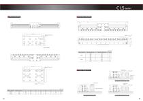
CLS series Slider Dimension Mounting Dimension Slider mounting hole 1 M3 x 6 Base mounting hole M3 x 5 Cable exit point Slider mounting hole 2 M3 x 5 Usage Suggestion Cable chain mounting plate Cable chain Cable chain support Motor Model Horizontal cable chain installation 1 Cable chain Motor Model Cable chain 17 Vertical cable chain installation Cable chain support Cable chain support Horizontal Cable chain installation 2
Open the catalog to page 5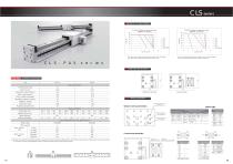
The chart is made with maximum velocity set to 5m/s. For higher The chart is made with maximum velocity set to 5m/s. For higher velocity or special requirements, please contact cpc velocity or special requirements, please contact cpc Motor parameters
Open the catalog to page 6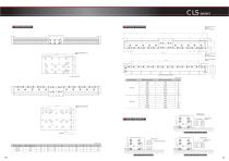
CLS series Slider Dimension Mounting Dimension Base mounting hole 1 Ø3.4 thru Ø6.5 Cbore, 3DP Base mounting hole 1 Ø3.4 thru Ø6.5 Cbore, 3.2DP Slider mounting hole 1 M4 x 7 Cable exit point Motor Model Slider mounting hole 2 M4 x 7 Base mounting hole 2 M4x8.5 Cable chain Cable chain support Usage Suggestion Cable chain mounting plate Horizontal cable chain installation 1 Cable chain support Cable chain support 12 Vertical cable chain installation Cable chain Cable chain Motor Model Horizontal cable chain installation 2
Open the catalog to page 7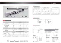
CLS series Dynamic Characteristics CLS-PB-X2 Dynamic response chart (300VDC unloaded) CLS-PB-X4 Dynamic response chart (300VDC unloaded) CLS-PB-X6 Dynamic response chart (300VDC unloaded) The chart is made with maximum velocity set to 5m/s. For higher velocity or special requirements, contact cpc The chart is made with maximum velocity set to 5m/s. For higher velocity or special requirements, contact cpc The chart is made with maximum velocity set to 5m/s. For higher velocity or special requirements, contact cpc CLS-PBX series Assembly Dimensions CLS-PBX Module Parameters PB-X6 Motor parameters...
Open the catalog to page 8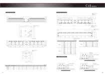
CLS series Motor Model Motor Model Cable chain mounting plate Cable chain Cable chain si Cable chain support
Open the catalog to page 9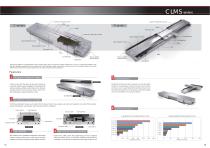
CLMS series Optical / Magnetic Scale Optical / Magnetic Encoder Magnetic Way Optical / Magnetic Encoder CN Connector Upper Dustproof Cover Coil Assem Assembly Coil Assembly Upper Dustproof Cover Side Dustproof Cover tproof Side Dustproof Cover Magnetic Way Block Base Coil Assembly Limit Switch Front and Back Stopper Blocks Front and Back ont k Stopper Blocks opper Limit Switch Direct drive systems can significantly improve productivity, yield, and dynamic motion performance. The cpc CLMS model utilizes a high precision positioning platform that is composed of a high load linear guide, high efficiency...
Open the catalog to page 10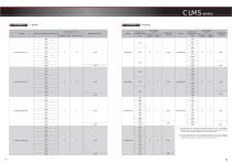
C-series P-series Model Maximum effective travel(mm) Magnetic scale Optical scale Maximum effective travel (mm) Magnetic Optical scale scale CLMS series Model Maximum effective travel (mm) Magnetic Optical scale scale '1. This is the standard value of the aluminum base fixed on a 0.01/300mm platform. We can reach higher specifications by changing the method and material to satisfy differing customer requirements. '2. This is the value derived from equipping the devicewith a 1pm encoder head. System accuracy can be increased further according to differing customer requirements to05, 0.2 and 0.1pm...
Open the catalog to page 11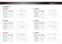
C-series Module Parameters CLMS series
Open the catalog to page 12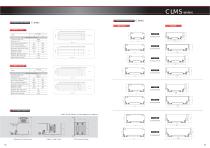
Module Parameters (Catalogue P23) * Size A, B and direction can be assigned by customer. a-On (Catalogue P27) (Catalogue P28) H-Side Cable Chain CO (Catalogue P29) (Catalogue P30) CLMS series loot lo or ip _
Open the catalog to page 13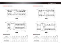
CLMS series Mounting Dimensions CLMS-CA2-55 Limit switch Limit switch M6 x 12 (Slider mounting hole) 10 M6 x 12 (Slider mounting hole) Limit switch Ø6.6 PTH Ø11 Countersunk hole, depth 6 (base mounting hole) Ø6.6 PTH Ø11 Countersunk hole, depth 6 (base mounting hole) Limit switch D M6 x 12 (Slider mounting hole) Limit switch 15 M6 x 12 (Slider mounting hole) Limit switch Limit switch Ø6.6 PTH Ø11 Countersunk hole, depth 6 (base mounting hole) Ø6.6 PTH Ø11 Countersunk hole, depth 6 (base mounting hole) Standard Specifications Standard Specifications Unit:mm Maximum effective travel (A+B) Maximum...
Open the catalog to page 14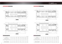
CLMS series Mounting Dimensions CLMS-CA6-75 M6 x 12 (Slider mounting hole) M6 x 12 (Slider mounting hole) Limit switch Limit switch Ø6.6 PTH Ø11 Countersunk hole, depth 6 (base mounting hole) Ø6.6 PTH Ø11 Countersunk hole, depth 6 (base mounting hole) Limit switch Limit switch Limit switch 25 M6 x 12 (Slider mounting hole) Limit switch Limit switch Ø6.6 PTH Ø11 Countersunk hole, depth 6 (base mounting hole) Ø6.6 PTH Ø11 Countersunk hole, depth 6 (base mounting hole) M6 x 12 (Slider mounting hole) Limit switch Standard Specifications Standard Specifications Unit:mm Maximum effective travel (A+B)...
Open the catalog to page 15All CPC catalogs and technical brochures
 Magnetic Way Encoder
1 Page
 Will1-D
2 Pages
 AC Linear Motor Servo Driver
6 Pages
 MR-M(SU/ZU)CATALOG
1 Page
 LM CATALOG
16 Pages
 AR/HR CATALOG
24 Pages

- Incremental encoder
- Measuring machine
- Servo-amplifier
- DC servo-amplifier
- Optical measurement system
- Linear encoder
- Distance measurement system
- Steel linear guide
- Ball bearing linear guide
- Incremental linear encoder
- Digital servo-amplifier
- Magnetic linear encoder
- Slide carriage block
- Compact linear guide
- Precision linear guide
- Aluminum linear guide
- Length measurement system
- RS-232 servo drive