- Catalogs
- COUDOINT S.A.S.
- Coudoint Edgewound Resistors
Coudoint Edgewound Resistors

Coudoint Edgewound Resistors
Catalog excerpts

Edgewound Resistors Hardware Reference Document 1101023 - Edition June 2009
Open the catalog to page 1
Hardware Reference _coi/oo/A/r Edgewound Resistors_ 3.2 Electrical and Thermal Specifications 4 Special Series and Models 5 Edgewound Resistor Assemblies Email: [email protected] Website: www.coudoint.com Address: 19 Avenue de la gare 78690 Les Essarts Le Roi FRANCE ^ Document 1101023 - Edition June 2009 Information and products subject to change without prior notice 2/25
Open the catalog to page 2
Hardware Reference _COt/OD/Nr Edgewound Resistors_ 1 General Description Edgewound resistors are characterized by : • high currents: continuous rated currents up to 103 Amps, in short time duty up to 1650 Amps • power ratings up to 3300 watts in continuous duty and natural-air cooling • low ohmic values from 0.018 ohm • high energy absorption during instantaneous discharges up to 527 kilojoules ♦> Series and models: Coudoint standard edgewound resistors are offered in the TOFIL Series and BC Series. Other special series and models are available as well. Resistor assemblies can be supplied...
Open the catalog to page 3
Hardware Reference Edgewound Resistors_ 2 Product Selection Guide The table below may be used to select a TOFIL or BC edgewound resistor for a given requirement: select the resistance alloy, then the cross-sectional size of the ribbon. Then, with the tables on the following pages, select the model corresponding to the required ohmic value or energy level. If a solution cannot be found, a resistor assembly may be required. An easy way to select a resistor is to describe what you need to us and we will suggest an optimized solution. ^ Document 1101023 - Edition June 2009 Information and products...
Open the catalog to page 4
Edgewound Resistors Hardware Reference 3 TOFIL and BC Series 3.1 General Description The resistors in the TOFIL and BC series use the same edgewound resistance coils, with a higher maximum number of turns for the BC series ( BC-8: 93 turns and BC-9: 105 turns) than the TOFIL series (84 turns maximum ). The electrical and thermal characteristics of the resistors are the same for a given line and number of turns . The terminals and optional intermediary lugs are the same in the two series, The difference between the resistors in the two series resides in the mechanical structure supporting the...
Open the catalog to page 5
Hardware Reference Edgewound Resistors_ - resistivity: 73 Q.mm2.m-1 at 25°C - coefficient of resistivity (vs. temperature): ~ 1000 ppm/°C. This alloy is suitable for applications where cost is the primary factor and where a low temperature coefficient of resistance is not required. • Alloy C: Chromium-aluminum - used for lines 9 to 14 - nominal composition: iron (~80%), chromium (~13%), aluminum (~5%) and manganese (~0.8%) - resistivity: 122 Q.mm2.m-1 at 25 °C - coefficient of resistivity (vs. temperature) lower than 100 ppm/°C. This alloy is used as a standard because of its very good cost/performance...
Open the catalog to page 6
Hardware Reference Edgewound Resistors_ ♦> Number of turns The approximate ohmic value per turn given in table 1 can be used to select a standard model in the TOFIL or BC series according to table 2 or to check the feasibility, the number of turns must be between: • 9 to 84 turns for TOFIL resistors These limits may vary depending on the required insulation voltage (standard dielectric voltage : 1,500 V). Table 2: Number of turns for the TOFIL and BC standard models ♦> Standard ohmic values Number of lines per type of alloy Table 3: Standard ohmic values for TOFIL and BC series ♦> Possible...
Open the catalog to page 7
Edgewound Resistors Hardware Reference TOFIL Series Models Diagram 1: Ohmic values (high values) vs. number of turns Document 1101023 – Edition June 2009 Information and products subject to change without prior notice
Open the catalog to page 8
Edgewound Resistors Hardware Reference TOFIL Series Models Diagram 2: Ohmic values (low values) vs. number of turns Document 1101023 – Edition June 2009 Information and products subject to change without prior notice
Open the catalog to page 9
Edgewound Resistors Hardware Reference 3.2.3 Continuous duty Rated current Rated current values are given in table 1 and diagrams 1 and 2. These values are for an ambient temperature of 25°C and for a temperature rise in the resistance coil of 375°C. For lines 4 to 21, the temperature rise in continuous duty can reach 450°C under specific conditions. The rated power can be significantly increased by forced-air cooling. Please contact us. Rated current derating When the ambient temperature is above 25°C, the rated current is reduced by a coefficient along the curve in diagram 3: Derating coefficient...
Open the catalog to page 10
Hardware Reference Edgewound Resistors_ 3.2.4 Instantaneous discharge This occurs when there is a quick discharge through the resistor - theoretically instantaneous, practically a few tenths of a second - which is not repeated, at least until the resistance coil is back to its initial temperature. These conditions, with the acceptable overload levels of the resistance coils (400°C for the lines 1 to 3 and 600°C for the other lines), make it possible for the resistor to absorb an energy of a value E given in table 4 for the standard models of the TOFIL and BC series: Table 4: Acceptable instantaneous...
Open the catalog to page 11
Hardware Reference Edgewound Resistors_ 3.2.5 Short time duty In this type of duty, the current flows through the resistor during a “current flow time” Ta, typically from one to several tens of seconds, then the resistor cools down during the rest time Tr, this value depends on the resistance coil and on the line number of the resistor. Table 5 gives the value of the rated current per line number for values of Ta from one second to one minute, with the minimum rest-time value Tr indicated for each line number: Table 5: Acceptable current levels per line in short time duty to Document 1101023...
Open the catalog to page 12
Hardware Reference _COt/OD/NrEdgewound Resistors_ 3.2.6 Intermittent periodic duty In this type of duty, the current flows across the resistor for a period of time T1, then stops (I = 0) during the rest time T2, and then a new cycle starts: the cycle time is T = T1 + T2 . At the end of the rest time, the resistance coil is at an intermediary temperature between the temperature which would be reached in continuous duty and the ambient temperature. Table 6 gives the acceptable currents for each line - except for those corresponding to the alloy B, which is not used in these applications due to...
Open the catalog to page 13All COUDOINT S.A.S. catalogs and technical brochures
 Rotary Rheostats
13 Pages
 Sliding Rheostats
20 Pages
 Woven Resistors
7 Pages
 Wirewound Resistors
23 Pages


- Potentiometer
- Wire-wound resistor
- Manual potentiometer
- Rotary potentiometer
- Power resistor
- Analog potentiometer
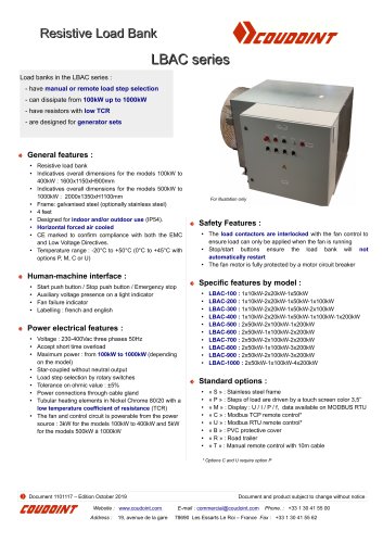
- Load bank
- Precision potentiometer
- Resistive load bank
- Wire-wound potentiometer
- Voltage resistor
- DC load bank
- High-voltage resistor
- AC load bank
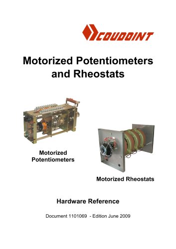
- Motorized potentiometer
- Test load bank
- Resistor with mounting bracket
- Mobile load bank
- Portable load bank
- Low-inductance resistor