Catalog excerpts

Support Designs for Reducing the Sag of Horizontally Supported Sheets Technical Information Paper TIP 303 Issued: November 2004 Supercedes: February 2003 Gautam Meda – Report L-5071 MAN Corning Incorporated, Corning NY Abstract At some stages in the manufacture of liquid crystal display panels, thin glass sheets are stacked horizontally in cassettes. The sheets sag due to gravity; with the ever-increasing sheet size and decreasing sheet thickness, the amount of sag has been increasing. Excessive sag is undesirable, since it limits the number of sheets that can be stacked in a cassette of given height. In this note, I describe some support designs that lead to reduced sag. Figure 1. Typical sheet support configuration. Introduction A common way of storing glass sheets during liquid crystal display manufacture is to stack them horizontally in cassettes. The sheets are typically supported on pins located near the edges of the sheet, as shown in Figure 1. One edge of the sheet, the ‘ front’ edge, must be free, to allow the sheet handling robot access. The glass sheets deflect due to gravity, and occupy a vertical range that is significantly larger than the sheet thickness. This vertical range is important, since it limits the number of sheets that can be stacked in a cassette of given height.
Open the catalog to page 1
In this note, the vertical spread, V, is defined as the difference between the maximum and the minimum vertical displacements of the mid-plane of the sheet. The sign convention is that upward displacements are positive, and downward displacements negative. The actual vertical range occupied by the glass sheet would be V + τ, where τ is the thickness of the sheet. The Problem The vertical spread V is proportional to the fourth power of the sheet size1. Hence, seemingly modest increases in sheet size can cause significant increases in vertical spread. The vertical spread is also inversely...
Open the catalog to page 2
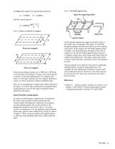
For four-row support, the optimal placement has Figure 5. Full-width support beams. Figure 4. Three-row and four-row support. Under optimal support, the supports touch the glass in the usable area, far inboard of the edges. So carefully designed padding should be provided to prevent scuffing of the glass. In this regard, the full-width support beams of Figure 5 are better than pins mounted at the ends of cantilevers: for the full-width support beams, the glassto-support contact area can be made much larger than for cantilevered support pins. The larger contact area leads to lower contact...
Open the catalog to page 3
North America and all other Countries Corning Display Technologies MP-HQ-W1 Corning, NY 14831 United States Telephone: +1 607-974-9000 Fax: +1 607-974-7097 Internet: www.corning.com/displaytechnologies Japan Corning Japan K.K. Main Office No. 35 Kowa Building, 1st Floor 1-14-14, Akasaka Minato-Ku, Tokyo 107-0052 Japan Telephone: +81 3-5562-2260 Fax: +81 3-5562-2263 Internet: www.corning.co.jp Nagoya Sales Office Nagoya Bldg., 7 F 4-6-18, Mei-eki, Nakamura-ku Nagoya-shi, Aichi 450-0002 Japan Telephone: +81 52-561-0341 Fax: +81 52-561-0348 China Corning (China) Ltd., Shanghai Representative...
Open the catalog to page 4All CORNING Display Technologies catalogs and technical brochures
-
Gorilla® Glass 5
2 Pages
-
Corning Iris®
2 Pages
-
Aspheres by Corning
2 Pages
-
UltraFlat™
2 Pages
-
Tropel® FlatMaster® MSP
2 Pages
-
Optical Solutions
4 Pages
-
EAGLE XG® Slim
2 Pages
-
Scoring of AMLCD Glass
4 Pages
Archived catalogs
-
Jade® Product Information Sheet
3 Pages
-
Jade® Material Information Sheet
2 Pages


