- Catalogs
- CORNING Display Technologies
- Fracture Analysis, a Basic Tool to Solve Breakage Issues (Part I)
Fracture Analysis, a Basic Tool to Solve Breakage Issues (Part I)
1 /9Pages

Fracture Analysis, a Basic Tool to Solve Breakage Issues (Part I)
1 /9Pages
Catalog excerpts
Fracture Analysis, a Basic Tool to Solve Breakage Issues Technical Information Paper TIP 201 Issued: November 2004 Supercedes: August 2000 Toshihiko Ono Corning Japan K. K., Shizuoka Technical Center 12117, Obuchi, Osuka, Ogasa, Shizuoka, 4371397, Japan the elimination of the origin and/or reducing the tensile stress. However, this solution can be applied only if location of origins and the kind of the tensile stresses are known. R. A. Allaire Corning Incorporated, Science and Technology Corning, NY, 14831, USA Biography T. Ono received his B. S. and M. S. degrees in inorganic chemistry from Nagaoka University of Technology, Niigata, Japan, in 1988 and 1990, respectively. In 1990, he joined the Shizuoka Technical Center of Corning Japan K. K. where he has been engaged in research and development of the finishing technologies of LCD glass substrate and other glasses. He has also proided extensive fracture analysis support to resolve breakage problems in Customer processes. Abstract Breakage of glass substrates in LCD manufacturing processes can cause serious problems of productivity and product quality/reliability. It is known that the mechanism associated with breakage is crack propagation by tensile stress concentration at a damaged point on the glass, which serves as an origin of the breakage [1]. Elimination of breakage requires Fracture analysis can provide information of both the tensile stress and the origin of breakage [2, 3]. This analytical technique gives important information in determining mechanism of breakage, such as direction of crack propagation, type of the stress, direction of impact and friction, location of the origin. All important information is "memorized" on the broken pieces and can be obtained through microscopic observation. A process where an origin is created is often different from the process where tensile stress is applied. The breakage mechanism can be understood by combining the information from fracture analysis with process information. The analysis method will be explained using actual cases. Also, the application of the method for optimization of cell-cutting process will be explained. Glass Breakage The mechanism of glass breakage is that crack propagates by tensile stress that concentrated at the origin, which is a small damage as cracks on the glass surface, or in the glass body. The relation of the failure stress and size of origin is explained with Eq. 1 [4],
Open the catalog to page 1
where Y is constant depending on the crack and sample shape, KIC is fracture toughness, and c is crack size. Glass having larger crack size, c, could broken at lower failure stress. Although the stress applied for glass is lower than the failure stress, crack can be propagated in the atmospheric condition, especially by water. This phenomenon is called Subcritical Crack Growth (SCG) caused by stress corrosion, in which the molecular of water cut the Si-O bonding chemically [5]. The durability of the stress corrosion of glass is indicated with n, crack growth parameter. The glass having large...
Open the catalog to page 2
Fracture Analysis When glass is broken, “footprints” of cracks are “memorized” on the fracture surfaces. These “footprints” map the fracture event and are strongly related to the origin creation, crack propagation and applied stress. Fracture analysis is structured with two parts, (1) observe the “footprints” on fracture surface to bring the information of origin and tensile stress, and (2) analyze the information with process information to identify the breakage mechanism. Table 1 shows the steps of the fracture analysis until obtaining the solution of the breakage issue [10]. Table 1. Process...
Open the catalog to page 3
Fig. 4 Secondary Wallner lines created by crack propagation with bending stress. Cracks run left to right (arrow mark). Hackle marks: Hackle marks are a definitive indication as to crack propagation direction. Typically two kinds of hackle marks can been seen, which are (1) twist hackle, appeared at region where the tensile stress tilted (twisted) from crack surface (Fig. 5) , and (2) mist hackle appeared around origin (Fig. 6). Mist hackles are commonly referred to as velocity hackle. Mirror Region Mist Hackle Fig. 6 Fracture surface around origin. Origin is surrounded with mirror region, which...
Open the catalog to page 4
(3) Identify crack propagation direction Actual Step of Fracture Analysis Procedure of the fracture analysis when a breakage is reported is explained using typical case [12]. This case is that breakage on three substrates were found when the sheets were unloaded from film deposition chamber. A crack was running a sheet to separate into two pieces. The crack shape of three sheets are shown in Fig. 8. (1) Collect all broken pieces The crack propagation direction is identified with observation of the Wallner lines or Hackle marks to look for a location of origin of the breakage. Not only the crack...
Open the catalog to page 5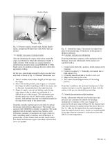
Hackle Marks Origin Origin Metal mark Wallner Lines Fig. 10 Fracture surface around origin. Radial Hackle marks, symmetrical Wallner lines with Arrest lines are existed (5) Identify root cause of origin creation After the identifying the origin, observation around the origin is performed to obtain the information related to origin creation. If the residue was existed, material identification should be done using SEM/EDX or FTIR. Small cracks by mechanical damage become visible after appropriate etching. On the case, ground edge around the origin was observed, and result is shown in Fig. 11. Obtained...
Open the catalog to page 6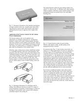
The typical fracture surface by good cutting (called “Cut surface”) is shown in Fig. 14. Median crack, approximately 100µm in depth is uniformly created, and the median crack propagated portion was smooth, due to low and stable breaking force. Glass surface Median crack Fig. 12 Schematic illustration of the identified mechanism of origin creation on the case. Actually, glass sheet slides with direction of arrow mark with fixed pin, and relative rubbing direction by pin is opposite (left to right in this figure). Median crack propagated portion Application of the Fracture Analysis for the Cutting...
Open the catalog to page 7All CORNING Display Technologies catalogs and technical brochures
 Corning Iris®
2 Pages
 Aspheres by Corning
2 Pages
 UltraFlat™
2 Pages
 Tropel® FlatMaster® MSP
2 Pages
 Optical Solutions
4 Pages
 EAGLE XG® Slim
2 Pages
 Scoring of AMLCD Glass
4 Pages


Archived catalogs
 Gorilla® Glass 5
2 Pages
 Jade® Material Information Sheet
2 Pages
 Jade® Product Information Sheet
3 Pages


