- Catalogs
- CORNING Display Technologies
- Effect of Scribing Wheel Dimensions on the Cutting of AMLCD Glass Substrates
Effect of Scribing Wheel Dimensions on the Cutting of AMLCD Glass Substrates
1 /9Pages

Effect of Scribing Wheel Dimensions on the Cutting of AMLCD Glass Substrates
1 /9Pages
Catalog excerpts
Effective of Scribing Wheel Dimensions on the Cutting of AMLCD Glass Substrates Technical Information Paper TIP 306 Issued: November 2004 Supercedes: xxxxx Toshihiko Ono Corning Japan K.K., Shizuoka Technical Center, 12117, Obuchi, Osuka, Ogasa, Shizuoka, 437-1397, Japan Kohichi Tanaka Nagaoka University of Technology, Department of Mechanical Engineering, Materials Science and Engineering Group, 1603-1, Kamitomioka-cho, Nagaoka, Niigata, 940-2188, Japan Abstract The scribe and break method for glass cutting is widely used to separate individual Liquid Crystal Display (LCD) panels from a larger mother substrate cell. Optimum glass scribing conditions including scribe wheel dimensions, scribing load, scribing speed, etc, have been determined based on practical manufacturing experience. However, there has been no systematic study to determine the scribing conditions necessary to avoid stray breakage. In this paper, the influence of the scribe wheel angle and diameter upon the scribing and the breaking of an Active Matrix Liquid Crystal Display (AMLCD) glass substrate, Corning Code1737F glass, was experimentally investigated for the case of simple single glass sheet separation. It was determined that an equation including the factors of scribe wheel tip angle and diameter can be used to predict median crack depth as a function of scribe load. It was further found that the breaking force of the scribed sheet was strongly influenced by the residual stress created during scribing. A wheel having a 130° tip angle and 4mm diameter demonstrated the best results for sheet separation in terms of the lowest breaking force without lateral crack propagation. In addition, increasing the time interval between scribing and separating was found to result in an increase in the breaking force required to separate glass substrate. Introduction The scribe and break method employing a tungsten carbide wheel is widely used to separate Liquid Crystal Display (LCD) panels from a large mother glass substrate cell. Scribing is a key process to glass separation (cutting). If the scribing conditions are not optimized, clean cutting of the mother cell sometimes becomes difficult due to the formation of lateral
Open the catalog to page 1
cracks which can propagate and become a source of glass chips. Although scribing conditions such as the scribe wheel dimensions, scribing load, scribing speed etc, have been optimized empirically by manufacturing experience; faulty cutting, in which the cutting line deviates from the scribed line, is still a significant process loss. There have been a few systematic studies to find the influence of scribing conditions on crack creation and propagation. Hara et al in 1950s,1,2 and Swain et al in 1980s3,4,5 discussed crack creation and propagation mechanisms during scribing and breaking in the...
Open the catalog to page 2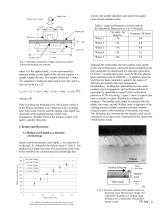
wheels with smaller diameters and steeper tip angles create deeper median cracks. Applied load Radii of rods =2.5mm Table 2 Angle and diameter of scribe wheels. By Mitsuboshi Diamond Ind. Co, A140 grade Tip angle, 2ψ Diameter, 2R [mm] [degree] Wheel 1 110 4.0 Wheel 2 Lower rods Median crack Fig. 1 Schematic illustration of upper and lower rods of four-point-bending test machine. where P is the applied load, c is the experimentally obtained median crack depth of the cleaved samples, t is sample length (40 mm), W is sample thickness (1.1mm), λ is separation of adjacent upper and lower rods, and...
Open the catalog to page 3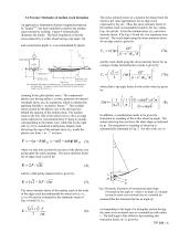
The stress intensity factor at a position far distant from the wheel is the value appropriates for an edge crack expressed by Eq. (4). Thus, the stress intensity factor of the median crack is presumably bound by the two values, Eqs. (4) and (6). From the residual stress σ22, and stress intensity factor, K by Eqs. (4) and (6), two equations were derived. The crack depth using the stress intensity factor for an edge crack is given by: 3.2 Fracture Mechanics of median crack formation An approach to indentation fracture toughness proposed by Tanaka10,11 has been modified to analyze the median crack...
Open the catalog to page 4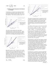
3.3 Influence of wheel tip angle and wheel diameter on scribability An experiment was designed to investigate the influence of scribe wheel tip angle on median crack depth. The 4mm diameter wheels described in Table 2 were used for this experiment. These results are plotted in Figs. 6 to 8. Predicted by Eq. (7b) without truncation 300 Median crack depth c, [mm] Predicted by Eq. (7b) with truncation Experimental data Predicted by Eq. (7a) without truncation 200 Fig. 8 Experimental and calculated median crack depth in Code 1737F glass scribed by a wheel having 4mm diameter and 130° tip angle. Predicted...
Open the catalog to page 5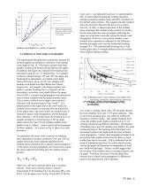
Predicted by Eq. (7b) without truncation Median Crack Depth [mm] Predicted by Eq. (7b) with truncation Experimental data Predicted by Eq. (7a) without truncation 200 Fig. 9 Experimental and calculated median crack depth in Soda lime glass scribed by a wheel having 4mm diameter and 110° tip angle. median crack depth in a variety of glasses. 3.4 Influence of wheel angle on breakability The experimental breaking force required to separate the scribed samples are plotted as a function of the median crack depth in Fig. 10. This figure includes data from samples scribed with wheels having different...
Open the catalog to page 6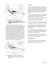
Upper bound, 0.8Pc Lower bound, 0.47Pc Median crack depth [µm] Fig. 11 Breaking force versus median crack depth of the specimens scribed by a wheel having various diameter 2.5mm (▲), 3.0mm (s), and 4.0mm (◊). 3.6 Influence of interval time between scribing and Tip angle was fixed to 120°. The standard interval of time between scribing and breaking was less than 30 minutes in this study. Fig. 12 is a plot of the breaking force versus median crack depth for samples broken approximately 60 and 90 minutes after scribing with a 2.5mm diameter scribe wheel. The onset point of increasing breaking force...
Open the catalog to page 7
References 1 M. Hara and J. Nakayama, “Study on the Cutting of Sheet Glass (part 1)”, Asahi Glass Co., Research Lab. Report, 6, [1], pp1-11, (1956). 2 M. Hara and J. Nakayama, “Study on the Cutting of Sheet Glass (part 2)”, Asahi Glass Co., Research Lab. Report, 6 [2], pp35-44, (1956). 3 M. V. Swain, “The Deformation Associated with the Scoring of Soda-Lime Float Glass with a Disc Cutter”, Glass Technology, Vol. 21, No. 6, pp290-296, (1980). 4 M. V. Swain and J. C. Metras, “Median Crack Initiation and Propagation Beneath a Disc Glass Cutter”, Glass Technology, Vol. 22, No. 5, pp222-230, (1981)....
Open the catalog to page 8All CORNING Display Technologies catalogs and technical brochures
 Corning Iris®
2 Pages
 Aspheres by Corning
2 Pages
 UltraFlat™
2 Pages
 Tropel® FlatMaster® MSP
2 Pages
 Optical Solutions
4 Pages
 EAGLE XG® Slim
2 Pages
 Scoring of AMLCD Glass
4 Pages


Archived catalogs
 Gorilla® Glass 5
2 Pages
 Jade® Material Information Sheet
2 Pages
 Jade® Product Information Sheet
3 Pages


