
Catalog excerpts

Cuttability of AMLCD Glass Substrates Using a Four-Point-Bending Test Technical Information Paper TIP 304 Issued: November 2004 Supercedes: February 2003 Toshihiko Ono Corning Japan K. K., Shizuoka Technical Center, Japan Koichi Tanaka Nagoka University of Technology, Niigata, Japan Abstract Glass cutting is one of the important processes in liquid-crystal display (LCD) manufacturing. Glass cutting consists of two processes, scribing and breaking. However, both processes have evolved through manufacturing experience and have not been analyzed theoretically, in particularly; no studies have been found which relate to the breaking process. In this study, theoretical and quantitative analysis is performed for the breaking process using a fourpoint-bending test of scribed sheet. From the results of the four-point-bending test, the breaking load of a scribed sheet was 40% lower than that of the theoretically calculated load due to the residual stress created by indentation and by sheet forming. For median crack depths greater than 100 µm, the breaking load increased to close to the calculated load due to stress relaxation by lateral crack growth. The four-point-bending test of scribed glass sheet is effective in identifying the breaking process, and is necessary to understand glass “cuttability”. In the manufacturing process of liquid-crystal-display (LCD) panels, a large mother-sheet glass is cut into smaller display-sized sheets by either dicing or scribing. Though the dicing method is generally better than the scribing method for dimensional precision, the glass surface is easily contaminated by glass debris and coolant and its process speed is 10 times slower than that of scribing method. With the requirements of LCD panel manufacturers such as clean glass surface and large production volume, the scribing method has been a major technology in this market because of higher throughput and cleaner process than dicing.
Open the catalog to page 1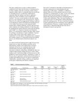
The glass-cutting process using a scribing method is composed of two steps: the first step is a scribing process to form a median crack line on the glass surface using a tungsten carbide wheel or a diamond chip; the second step is a breaking process, in which the scribed sheet is separated along the median crack line by applying a tensile stress due to bending or local compression methods1. The most serious problem in the glass-cutting process is mis-separation at the cleaving process, which is believed to be caused by inappropriate scribing conditions, or by applying too much load during...
Open the catalog to page 2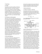
2. Experiments 2.1 Samples Five kinds of commercially available non-alkali LCD substrate glasses and one soda-lime glass were used in this study. The density, ρ, and Young’s modulus, E, Poisson’s ratio, ν, hardness, H, and fracture toughness, KIC, for these glasses are listed in Table 1, The thickness of all glass substrates was 1.1 mm. The substrates used for experiments in this paper were not the same as the samples used to obtain the mechanical properties shown in Table 1, because the substrates for the experiment were in as-received condition. i.e., no thermal treatment was made in...
Open the catalog to page 3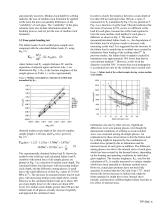
and generally incorrect. Median crack depth by scribing indicates the ease of median crack formation by applied scribe load, but does not quantify differences in the “cuttability” of each glass. The “cuttability” of the glass substrate must also include information about the breaking process, and not just the ease of median crack formation. 3.2 Four-point-bending test The failure loads of each scribed glass sample were compared with the calculated failure loads, Pƒ, using Eq, (2) 7. where failure load Pƒ, sample thickness W, and the separation of adjacent upper and lower rods, l, are...
Open the catalog to page 4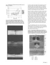
Figure 4. Differential of calculated and measured failure loads as a function of scribe load. Figure 5. Cross-sectional view of fractured specimens with median/lateral cracks in Code 7059 glass scribed at (a) 15.4N, median crack depth of 90 µm; (b) 18.6N, median crack depth of 110 µm and lateral cracks are left in the glass body; and (c) 21N, median crack depth of 125 µm and lateral cracks during scribing are left. In order to clarify why failure load irregularly increased when the median crack depth was larger than 100 µm, SLM observation on the scribed surface was performed for the...
Open the catalog to page 5
Figures 6(a) and 6(b) show a 7059 glass sample with 90and 110-µm median crack depths and lateral cracks remaining in the glass body. The compressed zone (hatched) and tensile (gray) zone exist symmetrically besides the median crack. The patterns are roughly in accordance with those of photo-elastic experiments, in which the compression zone is beneath the scribed portion, and the tensile zone is along the glass surface, symmetrically beside the median crack.10 In contrast to Figs. 6(a) and 6(b), Fig. 6(c) indicates that for the a sample with a median crack depth of 125 µm and with lateral...
Open the catalog to page 6
T. Ono received his B.S. and M.S. degrees in inorganic chemistry from Nagaoka University of Technology, Niigata Japan, in 1988 and 1990, respectively. In 1990, he joined the Shizuoka Technical Center of Corning Japan K. K. where he has been engaged in research and development of finishing technologies of LCD glass and memory disc substrates. Mr. Ono is a member of Ceramics Society of Japan. K. Tanaka is Professor of Materials Science and Engineering group in the department of Mechanical Engineering at Nagaoka University of Technology, Nagaoka, Niigata, He received his B.S. degree in...
Open the catalog to page 7All CORNING Display Technologies catalogs and technical brochures
-
Gorilla® Glass 5
2 Pages
-
Corning Iris®
2 Pages
-
Aspheres by Corning
2 Pages
-
UltraFlat™
2 Pages
-
Tropel® FlatMaster® MSP
2 Pages
-
Optical Solutions
4 Pages
-
EAGLE XG® Slim
2 Pages
-
Scoring of AMLCD Glass
4 Pages
Archived catalogs
-
Jade® Product Information Sheet
3 Pages
-
Jade® Material Information Sheet
2 Pages


