
- Catalogs
- COREMO OCMEA
- Caliper Brakes


Caliper Brakes

Caliper Brakes
- Thermal Capacity: Designed for emergency stops with a temperature change (∆T) of 170°C. Continuous thermal capacity varies by model, ranging from 0.2 kW to 20 kW.
- Braking Force: Mechanically actuated brakes have forces ranging from 1166 N to 39800 N, while pneumatic brakes range from 148 N to 3888 N at 6 bar pressure.
- Dynamic Torque: Calculated as the product of the braking force and the adjusted disc radius.
- Wear and Lining Thickness: Maximum total wear ranges from 6 mm to 16 mm, with new lining thicknesses from 5 mm to 16 mm.
- Initial Torque: Initial torque can be 30% to 50% less than the nominal value until the friction surfaces are properly worn in.
- Mounting Instructions: Brakes should be mounted horizontally to prevent the piston from pressing on the brake arms. For different mounting positions, consultation with the technical office is recommended.
- Various models are detailed with specific dimensions and weights, including MPA-M, A-M, B-M, D-M, E-M, EL-M, F-M, and G-M.
- Each model is available with different disc thickness options and specific mounting requirements.
- Tables provide detailed dimensions, product codes, and weights for each brake model.
- Charts illustrate the relationship between air pressure and torque for pneumatic models.
- Braking Force: Various models (A05, A1, A2, A3, B05, B1, B2, C300, C600, C1200, D05, D1, D2, D3, E3, E4, EL3, EL4, F05, F1, F2, F3) with forces ranging from 670 N to 36600 N at 6 bar.
- Dynamic Torque: Calculated as F • (disc radius in m - specific constant) = Nm, with constants varying per model.
- Max Total Wear: Ranges from 12 mm to 16 mm depending on the model.
- Thickness of New Lining: Varies from 11 mm to 16 mm.
- Continuous Thermal Capacity: Ranges from 1 kW to 20 kW, with higher capacities for double pad versions.
- Initial Torque: The initial torque can be 30% to 50% less than the nominal value until the friction facing and disc are worn in.
- Detailed dimensions and mounting instructions are provided for each model, including air volume and weight specifications.
- Charts illustrate the relationship between torque, disc diameter, and air pressure for different models.
Technical Data:
- Braking force varies across models, e.g., G1: 3610 N, G2: 7200 N, G3: 12500 N, G3.5: 19000 N.
- Dynamic torque is calculated as F multiplied by (disc radius in meters - specific constant).
- Maximum total wear and thickness of new lining are specified for each model.
- Continuous thermal capacity is provided, e.g., 14 kW for some models.
Procedures and Recommendations:
- Adjustments are necessary to maintain correct torque values as linings wear.
- Minimum release pressure is specified for each model, e.g., 4.5 bar for MPA-N.
Diagrams and Charts: Charts illustrate torque variation with lining wear and thermal capacity for emergency stops. Adjustments are recommended to ensure nominal torque values are maintained.
Product Dimensions: Dimensions and weights are provided for different brake models, including air volume and weight specifications.
Procedures and Adjustments: The document emphasizes the importance of adjusting the system to maintain the correct torque value as the linings wear. It includes warnings that the initial torque can be significantly less than the nominal value until the friction surfaces are properly worn in.
Standards and Recommendations: Recommendations are provided for maintaining optimal performance, including the adjustment of the system to restore nominal torque values. The document also highlights the benefits of combined brakes, which offer space and cost savings by integrating air applied and spring applied functions.
Charts and Diagrams: Several charts illustrate the variation of torque with each millimeter of lining wear, providing visual guidance for maintenance and adjustment. The diagrams also show the thermal capacity for emergency stops.
Key Data from Tables: The tables list product dimensions, air volume, and weight for each brake model, along with specific product codes. The tables also specify the number of springs required for different torque levels and the corresponding braking forces.
Critical Information:
- Maximum total wear for most models is 12 mm, with some variations.
- Continuous thermal capacity ranges from 1.7 kW to 20 kW depending on the model.
- Minimum release pressure is consistently 5 bar across models.
- Initial torque can be 30% to 50% less than the nominal value until the friction surfaces are worn in.
Procedures and Adjustments: The document emphasizes the importance of adjusting the system to maintain the correct torque value as the lining wears. It also notes that initial torque can be 30% to 50% less than the nominal value until the friction surfaces are properly worn in.
Standards and Recommendations: Torque values are specified for brakes with different numbers of springs, allowing for proportional adjustments. The document recommends using wear indicators and self-alignment features to ensure optimal performance and safety.
Features and Accessories: Various features such as wear compensation, inclined mounting kits, and double pads are available, some as standard and others as optional. These features are designed to enhance performance and meet modern machine requirements.
Diagrams and Charts: The document includes diagrams showing torque variation with lining wear and charts for air pressure and disc diameter. These visual aids help in understanding the performance characteristics of the brakes.
Additional Information: The document lists global distributors and provides contact information for the head office in Italy. It also highlights the availability of a wide range of devices and accessories for caliper brakes.
Catalog excerpts

CALIPER BRAKES
Open the catalog to page 1
COREMO OCMEA manufactures mechanical, pneumatic or hydraulic brakes and clutches for the industries of wire & cable, metalforming, steel, textile, paper, converting, packaging and for all other industrial applications. COREMO OCMEA, established 1960, is based in Assago - Milan (Italy) with a 3.200 m2 plant. COREMO OCMEA produit des freins et des embrayages mécaniques, pneumatiques ou hydrauliques pour les tréfileries, les câbleries, le travail du métal, la sidérurgie, le textile, le papier, l’emballage, le conditionnement et toutes autres applications industrielles. COREMO OCMEA fondée en 1960...
Open the catalog to page 2
CORRETTO UTILIZZO DEL PRODOTTO In ottemperanza al DPR 224/88 Direttiva CEE n. 85/374 definiamo i limiti di impiego per il corretto utilizzo del nostro prodotto garantendo la salvaguardia degli aspetti di sicurezza. Precauzioni al montaggio e manutenzione Agli addetti a tale funzione si consiglia l’impiego di equipaggiamenti idonei, guanti, occhiali od altro per la protezione adeguata da carichi e/o pesi. Parti rotanti Caratteristiche di progetto I FRENI A PINZA della COREMO OCMEA sono stati progettati per operare in conformità delle prestazioni e condizioni previste nel presente catalogo e delle...
Open the catalog to page 4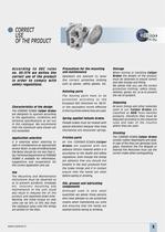
CORRECT USE OF THE PRODUCT According to EEC rules no. 85/374 we define the correct use of the product in order to comply with safety regulations. Precautions for the mounting and maintenance Operators are advised to wear the correct protective clothing such as gloves, safety glasses, etc. Rotating parts Characteristics of the design The COREMO OCMEA Caliper Brakes are designed to operate according to the application, conditions and technical specifications as set out in this catalogue. We recommend that the maximum data shown are not exceeded. The moving parts have to be protected according to...
Open the catalog to page 5
SELEZIONE SELEZIONE SELECTION SLITTAMENTO CONTINUO TENSIONING DOVE C Coppia dinamica Nm T Tensione sul materiale N D Diametro min e/o max della bobina m V Velocità lineare m/min Qc Calore prodotto in continuo kW n Velocità di rotazione min-1 C= Qc = n= T·D 2 T·V 60 · 103 V π·D FRENATURA DI INERZIE ELEVATE FRENATURA DI EMERGENZA DOVE C Coppia dinamica J Inerzia n Velocità di rotazione t Tempo di frenatura Q Calore prodotto/frenata Nm N m m/min kW min-1 HIGH INERTIA STOP Nm kgm 2 min-1 s kW J·n 9.55 · t J · n2 Q= 182.5 · 103 · t C= FRENATURA CICLICA DOVE C Coppia dinamica J Inerzia n Velocità di...
Open the catalog to page 6
SELECTION Slittamento continuo Tensioning - Tiro totale - Velocità - Diametro massimo bobina - Diametro minimo bobina - Coppia massima - Coppia minima - Velocità di rotazione massima - Velocità di rotazione minima - Calore da dissipare Selezione Selection total tension linear speed max. coil dia min. coil dia = 1800 Nm max torque = 672 Nm min torque = 22.7 min-1 max rotating speed = 8.5 min-1 min rotating speed - Inerzia da frenare - Velocità di rotazione - Tempo di frenatura - Tipo di freno: negativo - Coppia di frenatura - Calore prodotto ad ogni frenata No.1 brake D2 with 610 mm dia disc torque...
Open the catalog to page 7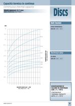
Capacità termica in continuo Continuous thermal capacity Discs Dischi spessore 12.7 mm. Disc thickness 12.7 mm. Dati tecnici kW GHISA SFEROIDALE DIAMETRO DISCO mm DISC DIAMETER mm UNI-ISO 1083 - 500.7 VELOCITÀ DISCO min-1 X 100 DISC SPEED min-1 X 100 Technical data SG IRON UNI-ISO 1083 - 500.7 DISSIPAZIONE DI CALORE IN CONTINUO CON ∆T = 170°C CONTINUOUS THERMAL CAPACITY WITH ∆T = 170°C www.coremo.it 7
Open the catalog to page 9
DISCHI Capacità termica frenata d’emergenza Spessore 12.7 mm. DISCO Ø 250 DISC Ø 250 DISCO Ø 356 DISC Ø 356 8 DISCO Ø 300 DISC Ø 300 DISCO Ø 406 DISC Ø 406 www.coremo.it
Open the catalog to page 10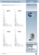
Thermal capacity - Emergency stop DISCS Thickness 12.7 mm. DISCO Ø 457 DISC Ø 457 DISCO Ø 610 DISC Ø 610 DISCO Ø 514 DISC Ø 514 DISCO Ø 711 DISC Ø 711 DISSIPAZIONE DI CALORE PER FRENATURA DI EMERGENZA CON ∆T = 170°C THERMAL CAPACITY FOR EMERGENCY STOP WITH ∆T = 170°C www.coremo.it 9
Open the catalog to page 11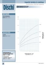
Capacita termica in continuo Continuous thermal capacity Dati tecnici GHISA SFEROIDALE Technical data THERMAL CAPACITY
Open the catalog to page 12
Capacità termica frenata d’emergenza Thermal capacity - Emergency stop Dischi spessore 25.4 mm Discs thickness 25.4 mm DISCO Ø 610 DISC Ø 610 DISCO Ø 762 DISC Ø 762 DISCO Ø 914 DISC Ø 914 Discs DISCO Ø 1065 DISC Ø 1065 DISSIPAZIONE DI CALORE PER FRENATURA DI EMERGENZA CON ∆T = 170°C THERMAL CAPACITY FOR EMERGENCY STOP WITH ∆T = 170°C www.coremo.it 11
Open the catalog to page 13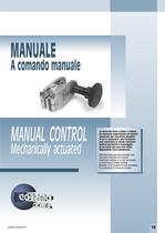
MANUALE A comando manuale MANUAL CONTROL Mechanically actuated www.coremo.it La serie dei freni a pinza a comando manuale rappresenta un’ottima soluzione per macchine semplici in cui è necessaria una frenatura non regolabile in modo continuo. Inoltre permette il montaggio di un freno nel caso non fosse disponibile l’aria compressa. Mechanically actuated brakes are the best solution for simple machines where it is not necessary a continuous brake tuning. Besides, if air supply is not available, it is possible to mount a brake. 13
Open the catalog to page 15
MANUALE Freni a comando manuale MPA-M ØC D A 18 Ø32 Ø10.5 B Lato Montaggio Mounting face 43 E 150 Ø Disco Disc ≥ F 70 81 DIMENSIONI/DIMENSIONS TIPO SIZE A B ØC D E F Peso Weight kg A2912 53 121 90 166 8 62 2.4 A2914 MPA-M Cod. Prodotto Product Number 51 129 90 175 12.7 68 2.4 Attenzione: La coppia iniziale può essere dal 30% al 50% in meno rispetto al valore nominale, fino all’assestamento del ferodo sul disco. Warning: The initial torque on new units can be 30% to 50% less than the catalogue value until the friction facing and friction disc are lapped or worn in. 14 www.coremo.it
Open the catalog to page 16
MANUAL Mechanically actuated brakes Dati tecnici Forza tangenziale F: MPA-M 2880 N 12 giri del volantino Coppia dinamica = F • (raggio del disco in m - 0.024) = Nm Usura max totale: 6 mm Spessore del ferodo nuovo: 5 mm MPA-M COPPIA Nm TORQUE Nm DIAMETRO DISCO mm DISC DIAMETER mm Dissipazione del calore in continuo Qc: 1 kW Technical data N° DI GIRI VOLANTINO No. TURNS OF HANDWHEEL Braking force F: MPA-M 2880 N 12 turns of handwheel Dynamic torque = F • (disc radius in m - 0.024) = Nm Max total wear: 6 mm Thickness of new lining: 5 mm Continuous thermal capacity Qc: 1 kW www.coremo.it 15
Open the catalog to page 17All COREMO OCMEA catalogs and technical brochures
 AIRING, Radial Units
14 Pages
 BI-M-VS
20 Pages
 MINI clutches and brakes
16 Pages
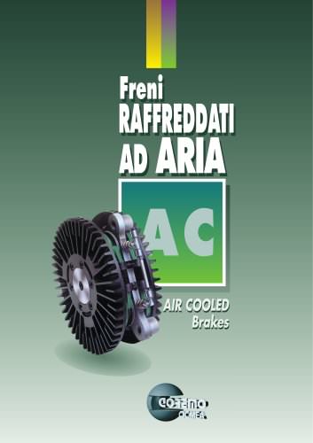 Air Cooled Brakes
16 Pages
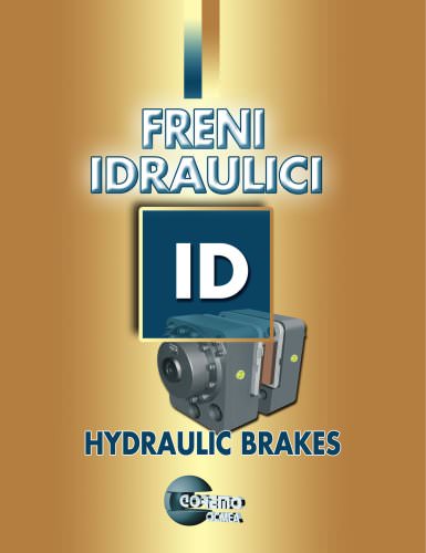 ID Hydraulic Brake
54 Pages
 SMART&CAB
16 Pages
 TB&SB
TB&SB22 Pages
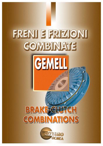

Archived catalogs
 Electric caliper brake
4 Pages