Catalog excerpts
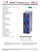
Compact CANopen digital servo drive for brush & brushless motors Control Modes • Profile Position-Velocity-Torque, Interpolated Position, Homing • Indexer, Point-to-Point, PVT • Camming, Gearing Command Interface • CANopen • ASCII and discrete I/O • Stepper commands • ±10V position/velocity/torque • PWM velocity/torque command • Master encoder (Gearing/Camming) Communications • CANopen • RS-232 Feedback Incremental • Digital quad A/B encoder • Analog sin/cos encoder • Panasonic Incremental A • Aux. encoder / encoder out Absolute • SSI • EnDat 2.1 & 2.2 • Absolute A • Tamagawa Absolute A • Panasonic Absolute A Format • Sanyo Denki Absolute A • BiSS (B&C) Other • Digital Halls I/O Digital • 6 High-speed inputs • 1 Motor over-temp input • 4 Opto-isolated inputs • 1 High-speed output • 3 Opto-isolated outputs • 1 Opto-isolated motor brake output I/O Analog • 1 Reference input, 12-bit Safe Torque Off (STO) • SIL 3, Category 3, PL d Dimensions: in [mm] • 7.54 x 4.55 x 2.13 [191.4 x 115.6 x 54.1] Add -R to the part number for resolver feedback description XPC sets new levels of performance, connectivity, and flexibility. CANopen communication provides a widely used cost-effective industrial bus. A wide range of absolute encoders are supported. Copley Controls, 20 Dan Road, Canton, MA 02021, USA P/N 16-01436 Rev 03 High resolution A/D converters ensure optimal current loop performance. Both isolated and high-speed non-isolated I/O are provided. For safety critical applications, re
Open the catalog to page 1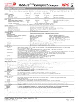
Compact CANopen general specifications Test conditions: Wye connected load: 2 mH line-line. Ambient temperature = 25 °C. Power input = 230 Vac, 60 Hz, 1 Ø MODEL Output CURRENT Peak Current Peak time Continuous current INPUT Adc (Arms, sinusoidal) s Adc (Arms, sinusoidal) POWER Mains voltage, phase, frequency 100~240 100~240 100~240 Vac, ±10%, 1Ø or 3Ø, 47~63 Hz 4.7 9.4 11.8 Arms 1Ø Maximum Mains Current, (Note 2) 2.6 5.2 6.5 Arms 3Ø +24 Vdc Control power +20~32 Vdc equired for operation (Note 3_ R 7.5 W (Typ, no load on +5V outputs), ≤ 18 W, (Max, both +5V outputs @ 500 mA) DIGITAL CONTROL...
Open the catalog to page 2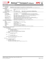
Compact CANopen general specifications status indicators Drive Status Bicolor LED, drive status indicated by color, and blinking or non-blinking condition NET Status RUN/ERR LEDs, status of CANopen bus indicated by color and blink codes to CAN Indicator Specification 303-3 REGENERATION Operation Solid state switch drives 60 W internal regen resistor Bus Capacitance 940 µF Continuous Power Capability 20 W Cut-In Voltage +HV > 390 Vdc ±2 Vdc Regen output is on, regen resistor is dissipating energy Drop-Out Voltage +HV < 380 Vdc ±2 Vdc Regen output is off, regen resistor not dissipating energy...
Open the catalog to page 3
Compact CANopen general specifications feedback Incremental: Digital Incremental Encoder Quadrature signals, (A, /A, B, /B, X, /X), differential (X, /X Index signals not required) 5 MHz maximum line frequency (20 M counts/sec), MAX3097 differential line receiver 121 Ω terminators between A & /A, B & /B inputs, 130 Ω between X & /X input Analog Incremental Encoder Sin/cos format (Sin+, Sin-, Cos+, Cos-), differential, 1 Vpeak-peak ±20%, ServoTube motor compatible BW > 300 kHz, 121 Ω terminating resistors between Sin+ & Sin-, Cos+ & Cos- inputs 12-bit resolution, BW > 300 kHz, with...
Open the catalog to page 4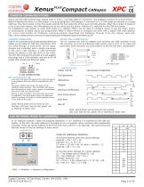
Compact CANopen canopen communications Xenus uses the CAN physical layer signals CAN_H, CAN_L, and CAN_GND for connection, and CANopen protocol for communication. Before installing the drive in a CAN system, it must be assigned a CAN address. A maximum of 127 CAN nodes are allowed on a single CAN bus. The rotary switch on the front panel controls the four lower bits of the seven-bit CAN address. When the number of nodes on a bus is less than sixteen, the CAN address can be set using only the switch. Address 0 is reserved for the CAN bus master. For installations with sixteen or more CAN...
Open the catalog to page 5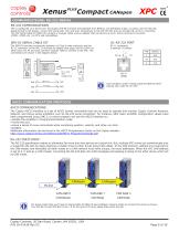
Compact CANopen communications: rs-232 serial RS-232 communications XPC is configured via a three-wire, full-duplex DTE RS-232 port that operates from 9600 to 115,200 Baud, 8 bits, no parity, and one stop bit. Signal format is full-duplex, 3-wire, DTE using RxD, TxD, and Gnd. Connections to the XPC RS-232 port are through J8, an RJ-11 connector. The XPC Serial Cable Kit (SER-CK) contains a modular cable, and an adapter that connects to a 9-pin, Sub-D serial port connector (COM1, COM2, etc.) on PC’s and compatibles. SER-CK serial cable kit The SER-CK provides connectivity between a D-Sub 9...
Open the catalog to page 6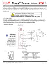
Compact CANopen safe torque off (sto) description The XPC provides the Safe Torque Off (STO) function as defined in IEC 61800-5-2. Three opto-couplers are provided which, when de-energized, prevent the upper and lower devices in the PWM outputs from being operated by the digital control core. This provides a positive OFF capability that cannot be overridden by the control firmware, or associated hardware components. When the opto-couplers are activated (current is flowing in the input diodes), the control core will be able to control the on/off state of the PWM outputs. installation Refer...
Open the catalog to page 7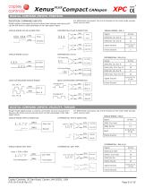
Compact CANopen digital command inputs: position position command inputs Digital position commands must be sourced from devices with active pullup and pull-down to take advantage of the high-speed inputs. Single-ended pulse & Direction For differential commands, the A & B channels of the multi-mode encoder ports may be used. differential pulse & Direction [IN3] Single-ended CU/CD Signal Ground Frame Ground differential CU/CD Frame Ground Signal Ground QUAD a/b ENCODER DIFFERENTIAL QUAD a/b ENCODER SINGLE-ENDED digital command inputs: velocity, torque Single-ended digital torque or velocity...
Open the catalog to page 8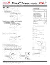
Compact CANopen Multi-mode encoder port as an input input types signals & pins POSITION COMMAND INPUTS: DIFFERENTIAL • Pulse & Direction • CW & CCW (Clockwise & Counter-Clockwise) • Encoder Quad A & B • Camming Encoder A & B input Signal Pulse, CW, Encoder A Quad Enc X, Absolute Clock Quad Enc /X, /Absolute Clock Enc S, Absolute (Clock) Data Input/Output Select Direction, CCW, Encoder B A/B/X signals from digital encoder Enc /S, / Absolute (Clock) Data Signal Ground Frame Ground CURRENT or VELOCITY COMMAND INPUTS: DIFFERENTIAL • Current or Velocity & Direction • Current or Velocity (+) &...
Open the catalog to page 9All Copley Controls catalogs and technical brochures
-
XenusPLUS Compact EtherCAT XEC
30 Pages
-
Control Networks
8 Pages
-
R-Series Guide
8 Pages
-
Selection Guide
24 Pages
-
Xenus R10
30 Pages
-
Accelnet R23
24 Pages
-
Accelnet R22
22 Pages
-
Accelnet R21
24 Pages
-
Accelnet R20
24 Pages
-
Accelus Card Development Kit
6 Pages
-
Accelus Card
8 Pages
-
ASP-X2 Accelus Panel Dual
10 Pages
-
Junus
10 Pages
-
CAN-PCI-02
2 Pages
-
CAN-IPM-01
8 Pages
-
Bantam
18 Pages
-
Bantam R30
18 Pages
-
503
6 Pages
-
Power Supply Subsystem
8 Pages
-
Shunt Regulator
2 Pages
-
Xenus PLUS 2-Axis CANopen
34 Pages
-
Xenus RoHS PLUS CANopen
28 Pages
-
Xenus PLUS 2-Axis EtherCAT
34 Pages
-
Xenus PLUS EtherCAT
28 Pages
-
Xenus Edge Filter
16 Pages
-
Regen Resistors
24 Pages
-
Xenus Micro
24 Pages
-
Accelus Card Development Kit
6 Pages
-
Accelus Card
8 Pages
-
Accelus Panel
10 Pages
-
Xenus XTL
30 Pages
-
Accelnet Plus EtherCAT Panel
18 Pages
-
Accelnet Micro Module and Kit
24 Pages
-
Accelnet Micro Panel
24 Pages
-
Accelnet Module Development Kit
8 Pages
-
Accelnet Module
14 Pages
-
Accelnet Panel ADP
24 Pages


