
- Catalogs
- Copley Controls
- Xenus R10

- Products
- Catalogs
- News & Trends
- Exhibitions
Xenus R10
Xenus R10
Catalog excerpts
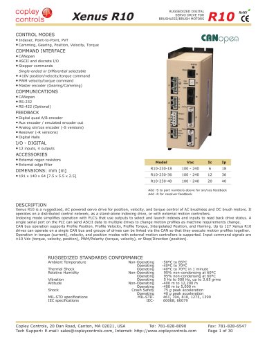
Xenus R10 RUGGEDIZED DIGITAL SERVO DRIVE FOR BRUSHLESS/BRUSH MOTORS R10 CONTROL MODES • Indexer, Point-to-Point, PVT • Camming, Gearing, Position, Velocity, Torque COMMAND INTERFACE • CANopen • ASCII and discrete I/O • Stepper commands RoHS R Single-ended or Differential selectable • ±10V position/velocity/torque command • PWM velocity/torque command • Master encoder (Gearing/Camming) COMMUNICATIONS • CANopen • RS-232 • RS-422 (Optional) FEEDBACK • Digital quad A/B encoder • Aux encoder / emulated encoder out • Analog sin/cos encoder (-S versions) • Resolver (-R versions) • Digital Halls I/O - DIGITAL • 12 inputs, 4 outputs ACCESSORIES • External regen resistors • External edge filter DIMENSIONS: mm [in] • 191 x 140 x 64 [7.5 x 5.5 x 2.5] Model Vac Ic Ip R10-230-18 100 - 240 6 18 R10-230-36 100 - 240 12 36 R10-230-40 100 - 240 20 40 Add -S to part numbers above for sin/cos feedback Add -R for resolver feedback DESCRIPTION Xenus R10 is a ruggedized, AC powered servo drive for position, velocity, and torque control of AC brushless and DC brush motors. It operates on a distributed control network, as a stand-alone indexing drive, or with external motion controllers. Indexing mode simplifies operation with PLC’s that use outputs to select and launch indexes and inputs to read back drive status. A single serial port on the PLC can send ASCII data to multiple drives to change motion profiles as machine requirements change. CAN bus operation supports Profile Position, Profile Velocity, Profile Torque, Interpolated Position, and Homing. Up to 127 Xenus R10 drives can operate on a single CAN bus and groups of drives can be linked via the CAN so that they execute motion profiles together. Operation in torque (current), velocity, and position modes with external motion controllers is supported. Input command signals are ±10 Vdc (torque, velocity, position), PWM/Polarity (torque, velocity), or Step/Direction (position). RUGGEDIZED STANDARDS CONFORMANCE Ambient Temperature Thermal Shock Relative Humidity Vibration Altitude Shock MIL-STD specifications IEC specifications Non-Operating Operating Operating Non-Operating Operating Operating Non-Operating Operating Crash Safety Operating MIL-STD- IEC- -50ºC to 85ºC -40ºC to 70ºC -40ºC to 70ºC in 1 minute 95% non-condensing at 60ºC 95% non-condensing at 60ºC 5 Hz to 500 Hz, up to 3.85 grms -400 m to 12,200 m -400 m to 5,000 m 75 g peak acceleration 40 g peak acceleration 461, 704, 810, 1275, 1399 60068, 60079 Copley Controls, 20 Dan Road, Canton, MA 02021, USA Tel: 781-828-8090 Tech Support: E-mail: [email protected], Internet: http://www.copleycontrols.com Fax: 781-828-6547 Page 1 of 30
Open the catalog to page 1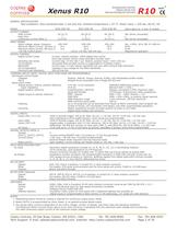
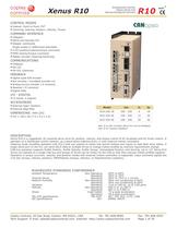
Xenus R10 RUGGEDIZED DIGITAL SERVO DRIVE FOR BRUSHLESS/BRUSH MOTORS R10 RoHS GENERAL SPECIFICATIONS Test conditions: Wye connected load: 2 mH line-line. Ambient temperature = 25 °C. Power input = 230 Vac, 60 Hz, 1Ø MODEL R10-230-18 R10-230-36 R10-230-40 Same specs for -S and -R models OUTPUT CURRENT Peak Current 18 (12.7) 36 (25.5) 40 (28.3) Adc (Arms, sinusoidal) Peak time 1 1 1 s Continuous current (Note 1) 6 (4.24) 12 (8.5) 20 (14.1) Adc (Arms, sinusoidal) INPUT POWER Mains voltage, phase, frequency 100~240 100~240 100~240 Vac, ±10%, 1Ø or 3Ø, 47~400 Hz 10.1 20.0 20.0 Arms Maximum Mains Current,...
Open the catalog to page 2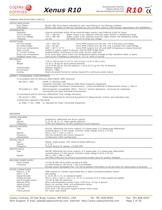
Xenus R10 RUGGEDIZED DIGITAL SERVO DRIVE FOR BRUSHLESS/BRUSH MOTORS R10 RoHS GENERAL SPECIFICATIONS (CONT’D) STATUS INDICATORS Drive Status CAN Status REGENERATION Operation Cut-In Voltage Drop-Out Voltage Tolerance PROTECTIONS HV Overvoltage HV Undervoltage Drive over temperature Short circuits I2T Current limiting Motor over temperature Feedback power loss MECHANICAL Size Weight Contaminants Environment Cooling Bicolor LED, drive status indicated by color, and blinking or non-blinking condition Bicolor LED, status of CAN bus indicated by color and blink codes to CAN Indicator Specification...
Open the catalog to page 3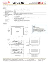
Xenus R10 RUGGEDIZED DIGITAL SERVO DRIVE FOR BRUSHLESS/BRUSH MOTORS R10 RoHS FEEDBACK SPECIFICATIONS (CONT’D) RESOLVER RESOLVER Type Resolution Reference frequency Reference voltage Reference maximum current Maximum RPM Brushless, single-speed, 1:1 to 2:1 programmable transformation ratio 14 bits (equivalent to a 4096 line quadrature encoder) 7.5 kHz 2.8 Vrms, auto-adjustable by the drive to maximize feedback 100 mA 10,000+ ENCODER EMULATION Resolution Buffered encoder outputs Programmable to 16,384 counts/rev (4096 line encoder equivalent) 26C31 differential line driver MOTOR CONNECTIONS Phase...
Open the catalog to page 4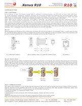
Xenus R10 R10 RUGGEDIZED DIGITAL SERVO DRIVE FOR BRUSHLESS/BRUSH MOTORS RoHS COMMUNICATIONS CME 2 SOFTWARE Drive setup is fast and easy using CME 2 software communicating via RS-232 or over the CAN bus. All of the operations needed to configure the drive are accessible through this powerful and intuitive program. Autophasing of brushless motor Hall sensors and phase wires eliminates “wire and try”. Connections are made once and CME 2 does the rest thereafter. Encoder wire swapping to establish the direction of positive motion is eliminated. Motor data can be saved as .ccm files. Drive data is...
Open the catalog to page 5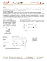
Xenus R10 R10 RUGGEDIZED DIGITAL SERVO DRIVE FOR BRUSHLESS/BRUSH MOTORS RoHS COMMUNICATIONS (CONTINUED) CANOPEN Based on the CAN V2.0b physical layer, a robust, two-wire communication bus originally designed for automotive use where low-cost and noise-immunity are essential, CANopen adds support for motion-control devices and command synchronization. The result is a highly effective combination of data-rate and low cost for multi-axis motion control systems. Device synchronization enables multiple axes to coordinate moves as if they were driven from a single control card. CANOPEN COMMUNICATION...
Open the catalog to page 6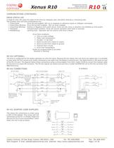
Xenus R10 RUGGEDIZED DIGITAL SERVO DRIVE FOR BRUSHLESS/BRUSH MOTORS R10 RoHS COMMUNICATIONS (CONTINUED) DRIVE STATUS LED A single bi-color LED gives the state of the drive by changing color, and either blinking or remaining solid. The possible color and blink combinations are: • Green/Solid: Drive OK and enabled. Will run in response to reference inputs or CANopen commands. • Green/Slow-Blinking: Drive OK but NOT-enabled. Will run when enabled. • Green/Fast-Blinking: Positive or Negative limit switch active. Drive will only move in direction not inhibited by limit switch. • Red/Solid: Transient...
Open the catalog to page 7All Copley Controls catalogs and technical brochures
 XenusPLUS Compact EtherCAT XEC
30 Pages
 XenusPLUS Compact CANopen XPC
30 Pages
 Control Networks
8 Pages
 R-Series Guide
8 Pages
 Selection Guide
24 Pages
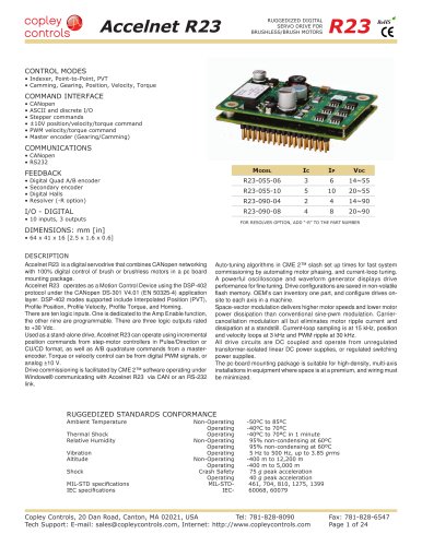 Accelnet R23
24 Pages
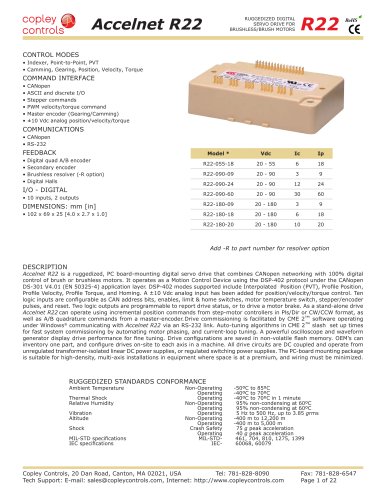 Accelnet R22
22 Pages
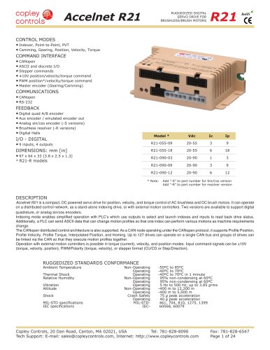 Accelnet R21
24 Pages
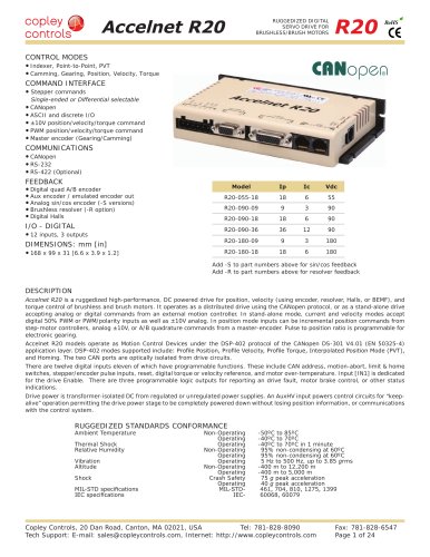 Accelnet R20
24 Pages
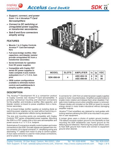 Accelus Card Development Kit
6 Pages
 Accelus Card
8 Pages
 ASP-X2 Accelus Panel Dual
10 Pages
 Junus
Junus10 Pages
 CAN-PCI-02
2 Pages
 CAN-IPM-01
8 Pages
 Bantam
18 Pages
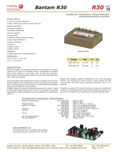 Bantam R30
18 Pages
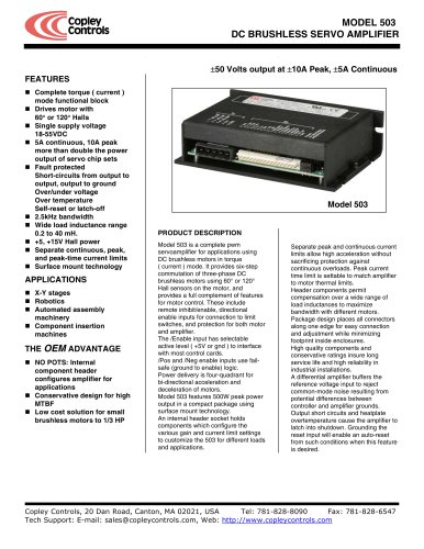 503
5036 Pages
 Power Supply Subsystem
8 Pages
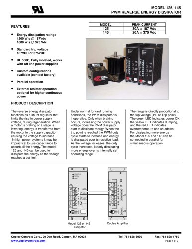 Shunt Regulator
2 Pages
 Xenus PLUS 2-Axis CANopen
34 Pages
 Xenus RoHS PLUS CANopen
28 Pages
 Xenus PLUS 2-Axis EtherCAT
34 Pages
 Xenus PLUS EtherCAT
28 Pages
 Xenus Edge Filter
16 Pages
 Regen Resistors
24 Pages
 Xenus Micro
24 Pages
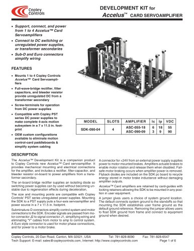 Accelus Card Development Kit
6 Pages
 Accelus Card
8 Pages
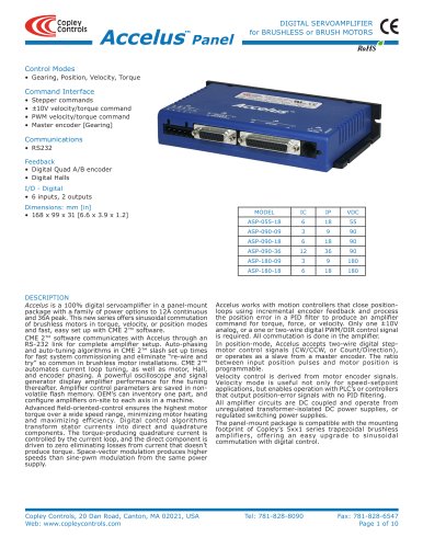 Accelus Panel
10 Pages
 Xenus XTL
30 Pages
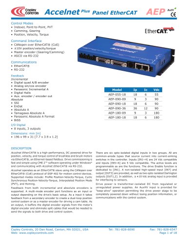 Accelnet Plus EtherCAT Panel
18 Pages
 Accelnet Micro Module and Kit
24 Pages
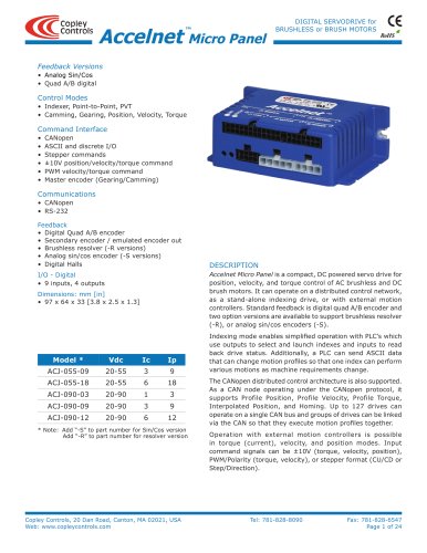 Accelnet Micro Panel
24 Pages
 Accelnet Module Development Kit
8 Pages
 Accelnet Module
14 Pages
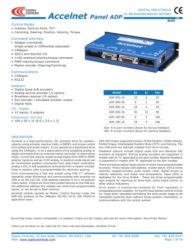 Accelnet Panel ADP
24 Pages





- Analog I/O
- Servo-amplifier
- Motor controller
- DC servo-amplifier
- Fieldbus servo-drive
- DC motor controller
- AC servo-amplifier
- Brushless servo-amplifier
- Stepper motor controller
- Communication interface card
- EtherCAT servo-amplifier
- Compact servo-amplifier
- CANopen servo-amplifier
- Digital servo-amplifier
- Stepper servo drive
- Industrial interface expansion card
- CANopen I/O
- Brushless motor control
- Digital input motor controller