- Catalogs
- Copley Controls
- Xenus PLUS 2-Axis CANopen
Xenus PLUS 2-Axis CANopen
1 /34Pages

Xenus PLUS 2-Axis CANopen
1 /34Pages
Catalog excerpts

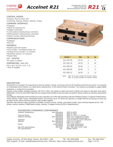
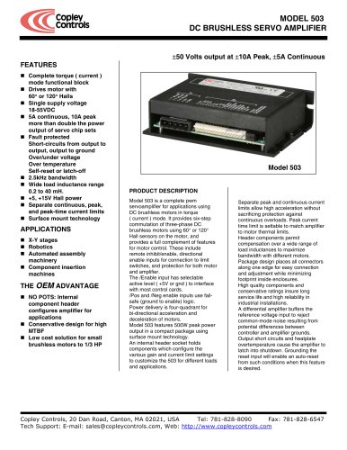
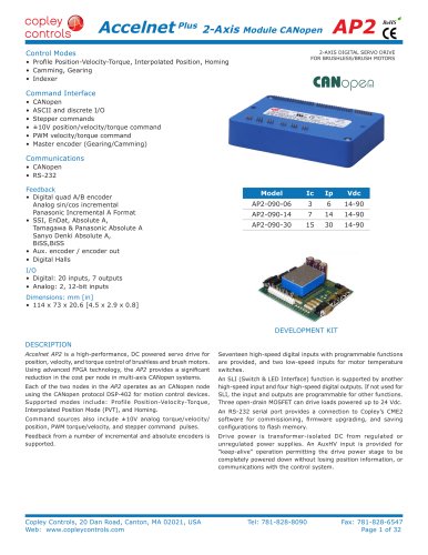
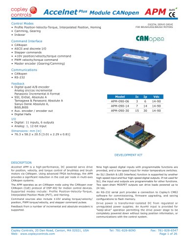
Xenus PLUS 2-Axis CANopen XP2 RoHS 2-AXIS DIGITAL SERVO DRIVE FOR BRUSHLESS/BRUSH MOTORS Control Modes • Profile Position-Velocity-Torque, Interpolated Position, Homing • Camming, Gearing • Indexer Command Interface • CANopen • ASCII and discrete I/O • Stepper commands • ±10V position/velocity/torque • PWM velocity/torque command • Master encoder (Gearing/Camming) Communications • CANopen DS-402 • RS-232 Accessories • External regen resistors Feedback Incremental Encoders • Digital quad A/B Analog Sin/Cos Panasonic Incremental A Format • Aux. quad A/B encoder / encoder out Absolute Encoders • SSI, EnDat, Absolute A, Tamagawa & Panasonic Absolute A Sanyo Denki Absolute A, Biss Resolver (-R option) • Brushless Resolver Other • Digital Halls Safe Torque Off (STO) • SIL 3, Category 4, PL e I/O Digital • 22 inputs, 7 outputs • 2 High-speed, non-isolated outputs I/O Analog • 2, 14-bit inputs Dimensions: in [mm] • 9.24 [234.7] x 5.77 [146.6] x 2.31 [58.7] Model Vac Ic Ip XP2-230-20 100~240 10 20 Current ratings are for each axis Add -R for resolver feedback option DESCRIPTION XP2 set new levels of performance, connectivity, and flexibility. CANopen communications provides a widely used cost-effective industrial bus. A wide range of absolute encoders are supported. High resolution A/D converters ensure optimal current loop performance. Both isolated and high-speed non-isolated I/O are provided. For safety critical applications, redundant power stage enable inputs (STO) can be employed. Copley Controls, 20 Dan Road, Canton, MA 02021, USA Tel: 781-828-8090 Tech Support: E-mail: [email protected], Web: http://www.copleycontrols.com Fax: 781-828-6547 Page 1 of 34
Open the catalog to page 1
Xenus PLUS 2-Axis CANopen XP2 RoHS GENERAL SPECIFICATIONS Test conditions: Wye connected load: 2 mH line-line. Ambient temperature = 25° C. Power input = 230 Vac, 60 Hz, 1 Ø MODEL XP2-230-20 OUTPUT CURRENT (EACH AXIS) Peak Current 20 (14) Adc (Arms, sinusoidal) Peak time 1 s Continuous current (Heatsink required) 10 (7) Adc (Arms, sinusoidal) INPUT POWER Mains voltage, phase, frequency 100~240 Vac, ±10%, 1 Ø or 3 Ø, 47~63 Hz Maximum Mains Current, 1Ø (Note 2) 20 Arms Maximum Mains current, 3Ø (Note 2) 15.4 Arms +24 Vdc Control power +20 to +32 Vdc, 0.5~1.1 Adc (Note 3) Required for operation...
Open the catalog to page 2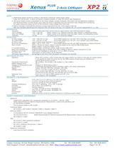
1. Heatsinking and/or forced-air cooling is required for continuous output power rating. Order XP2-230-20 with -H option for factory-installed heatsink, or order XP2-HK for user-installed kit. 3. With no encoders connected the minimum current requirement for the +24V supply is 500 mA With four encoders operating at the maximum 400 mA rating of the four +5V supplies the +24 current requirement is ~1.1 Adc Cut-in Voltage Drop-Out Voltage Internal solid-state switch drives external regen resistor (see Ordering Guide for types) + HV > 390 Vdc Regen output is on, (optional external) regen resistor...
Open the catalog to page 3
Xenus PLUS 2-Axis CANopen XP2 RoHS FEEDBACK SPECIFICATIONS FEEDBACK Incremental: Digital Incremental Encoder Quadrature signals, (A, /A, B, /B, X, /X), differential (X, /X Index signals not required) 5 MHz maximum line frequency (20 M counts/sec) MAX3097 differential line receiver with 121 Ω terminating resistor between complementary inputs Analog Incremental Encoder Sin/cos format (sin+, sin-, cos+, cos-), differential, 1 Vpeak-peak, ServoTube motor compatible, BW > 300 kHz, 121 Ω terminating resistor between complementary inputs Analog Index signal Differential, 121 Ω terminating resistor between...
Open the catalog to page 4
Xenus PLUS 2-Axis CANopen XP2 RoHS CANOPEN CONNECTORS Dual RJ-45 connectors that accept standard Ethernet cables are provided for CAN bus connectivity. Pins are wired-through so that drives can be daisy-chained and controlled with a single connection to the user’s CAN interface. A CAN terminator should be placed in the last drive in the chain. The XTL-NK connector kit provides a D-Sub adapter that plugs into a CAN controller and has an RJ-45 socket that accepts the Ethernet cable. CANOPEN Based on the CAN V2.0b physical layer, a robust, two-wire communication bus originally designed for automotive...
Open the catalog to page 5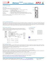
Xenus PLUS 2-Axis CANopen XP2 RoHS COMMUNICATIONS AMP LEDS Bi-color LEDs on J7 give the state of each axis of the Xenus drive. Colors do not alternate, and can be solid ON or blinking: Green/Solid = Drive OK and enabled. Will run in response to reference inputs or CANopen commands. Green/Slow-Blinking = Drive OK but NOT-enabled. Will run when enabled. Green/Fast-Blinking = Positive or Negative limit switch active. Drive will only move in direction not inhibited by limit switch. Red/Solid = Transient fault condition. Drive will resume operation when fault is removed. Red/Blinking = Latching fault....
Open the catalog to page 6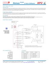
Xenus PLUS XP2 2-Axis CANopen RoHS SAFE TORQUE OFF (STO) DESCRIPTION The XP2 provides the Safe Torque Off (STO) function as defined in IEC 61800-5-2. Three opto-couplers are provided which, when de-energized, prevent the upper and lower devices in the PWM outputs from being operated by the digital control core. This provides a positive OFF capability that cannot be overridden by the control firmware, or associated hardware components. When the opto-couplers are activated (current is flowing in the input diodes), the control core will be able to control the on/off state of the PWM outputs. FUNCTIONAL...
Open the catalog to page 7
Xenus PLUS 2-Axis CANopen XP2 RoHS COMMAND INPUTS DIGITAL POSITION Digital position commands can be in either single-ended or differential format. Single-ended signals should be sourced from devices with active pull-up and pull-down to take advantage of the high-speed inputs. Differential inputs have 121 Ω line-terminators. SINGLE-ENDED PULSE & DIRECTION IN4(14) DIFFERENTIAL PULSE & DIRECTION IN2(12) Pulse PULSE+ IN3(13) IN5(15) PULSE- Direction COMMAND SINGLE-ENDED IN4(14) DIRECTION+ Axis A Axis B Pls, Enc A 10 15 Dir, Enc B SINGLE-ENDED CU/CD Signal DIRECTION- IN5(15) 11 30 DIFFERENTIAL CU/CD...
Open the catalog to page 8All Copley Controls catalogs and technical brochures
 XenusPLUS Compact EtherCAT XEC
30 Pages
 XenusPLUS Compact CANopen XPC
30 Pages
 Control Networks
8 Pages
 R-Series Guide
8 Pages
 Selection Guide
24 Pages
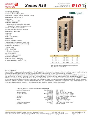 Xenus R10
30 Pages
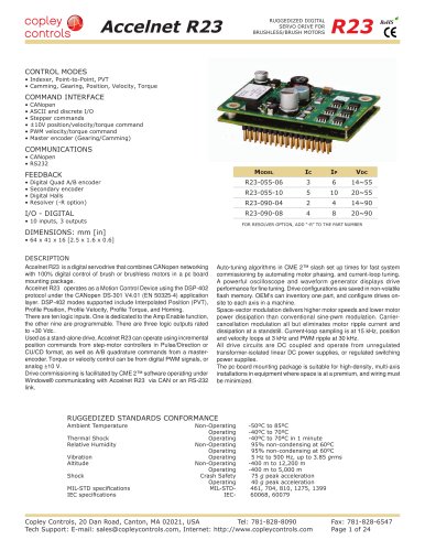 Accelnet R23
24 Pages
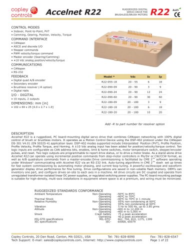 Accelnet R22
22 Pages
 Accelnet R21
24 Pages
 Accelnet R20
24 Pages
 Accelus Card Development Kit
6 Pages
 Accelus Card
8 Pages
 ASP-X2 Accelus Panel Dual
10 Pages
 Junus
Junus10 Pages
 CAN-PCI-02
2 Pages
 CAN-IPM-01
8 Pages
 Bantam
18 Pages
 Bantam R30
18 Pages
 503
5036 Pages
 Power Supply Subsystem
8 Pages
 Shunt Regulator
2 Pages
 Xenus RoHS PLUS CANopen
28 Pages
 Xenus PLUS 2-Axis EtherCAT
34 Pages
 Xenus PLUS EtherCAT
28 Pages
 Xenus Edge Filter
16 Pages
 Regen Resistors
24 Pages
 Xenus Micro
24 Pages
 Accelus Card Development Kit
6 Pages
 Accelus Card
8 Pages
 Accelus Panel
10 Pages
 Xenus XTL
30 Pages
 Accelnet Plus EtherCAT Panel
18 Pages
 Accelnet Micro Module and Kit
24 Pages
 Accelnet Micro Panel
24 Pages
 Accelnet Module Development Kit
8 Pages
 Accelnet Module
14 Pages
 Accelnet Panel ADP
24 Pages


- Digital I/O
- Analog I/O
- Servo-amplifier
- Motor controller
- DC servo-amplifier
- Fieldbus servo-drive
- DC motor controller
- Stepper motor controller
- AC servo-amplifier
- Communication interface card
- Brushless servo drive
- Compact servo-amplifier
- EtherCAT servo-amplifier
- Digital servo-amplifier
- Industrial interface expansion card
- CANopen servo-amplifier
- CANopen I/O
- Brushless motor control
- Digital input motor controller
- I/O card