- Catalogs
- Copley Controls
- Stepnet Module Development Kit
Stepnet Module Development Kit
1 /8Pages

Stepnet Module Development Kit
1 /8Pages
Catalog excerpts
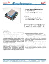
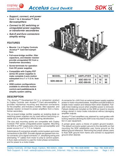
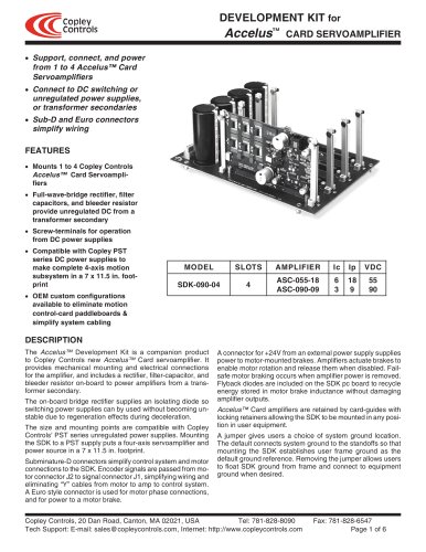
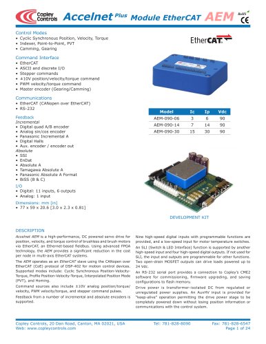
Stepnet Module DevKit • For Rev 4 PC boards TDK Provides Mounting & Connections for Stepnet Module CANopen Stepping Motor Driver FEATURES • Develop & Debug Stepnet projects then transfer design to OEM pc board. MODEL DRIVER Ic Ip VDC TDK-075-01 STM-075-07 5 7 75 DESCRIPTION The Development Kit is a companion product to Copley Controls’ new Stepnet Module stepping motor driver. It provides mechanical mounting and electrical connections for the driver so users can quickly connect Stepnet and begin to develop applications. Euro style screw-terminal connector blocks simplify connections for power and motor phase-windings. SubD connectors have compatible pinouts with Accelus™ and Accelnet™ panel amplifiers for command, I/O and optional motor encoder signals. A 16-position rotary switch connects to Stepnet I/O pins for selection of the CAN bus device address. Individual toggle switches are wired to other I/O pins to simulate limit switches, motor overtemperature sensor, and home switch functions. Jumpers permit these switches to be disconnected so that the I/O pins can connect to user equipment through the Sub-D connectors. A 121Ω resistor can be jumpered in or out as a terminator for the CAN bus signals if the development kit is the last device on a CAN bus. Four LED’s can be jumpered in or out to the Stepnet logic outputs. These give an easy read-out of the output status for debugging. Motor encoder signals are connected through from the motor connector to the signal connector eliminating split cables in cases where the Stepnet is operating as a stand-alone servo-motor control. In these cases, the external controller uses the encoder for position feedback, and Stepnet operates the stepping motor as a DC brushless motor. Copley Controls, 20 Dan Road, Canton, MA 02021, USA Tel: 781-828-8090 Fax: 781-828-6547 Tech Support: E-mail: [email protected], Internet: http://www.copleycontrols.com Page 1 of 8
Open the catalog to page 1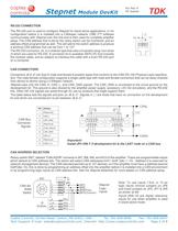
Stepnet Module DevKit For Rev 4 PC boards TDK RS-232 CONNECTION The RS-232 port is used to configure Stepnet for stand-alone applications, or for configuration before it is installed into a CANopen network. CME 2™ software communicates with Stepnet over this link and is then used for complete amplifier setup. The CAN address that is set by the rotary switch can be monitored, and an address offset programmed as well. This will add to the switch address to produce a working CAN address that can be from 1 to 127. The RS-232 connector, J4, is a modular type that uses a 6-position plug, four wires...
Open the catalog to page 2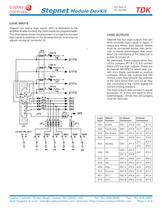
For Rev 4 PC boards Stepnet Module DevKit TDK LOGIC INPUTS Stepnet has twelve logic inputs. [IN1] is dedicated to the amplifier enable function, the other inputs are programmable. The chart below shows the placement of jumpers to connect logic inputs to switches on the development kit, or to external signals via signal connector J3: LOGIC OUTPUTS Stepnet has four logic outputs that can drive controller logic inputs or relays. If relays are driven, then flyback diodes must be connected across their terminals to clamp overvoltages that occur when the inductance of the relay coil is suddenly turned...
Open the catalog to page 3
Stepnet Module DevKit ENCODER CONNECTIONS TDK POWER SUPPLIES The development kit has a 26C32A differential line receiver for the motor encoder inputs. Differential-output encoders are preferred for best signal quality and noise rejection. Wiring should be twisted-pairs, preferably with a shield for each pair. To eliminate noise on the encoder signals caused by reflections on the cables, it is good practice to terminate signal-pairs with a resistor that matches the characteristic impedance of the cable. On the development kit,121Ω resistors are provided for this purpose. Jumpers at JP9-A, B, and...
Open the catalog to page 4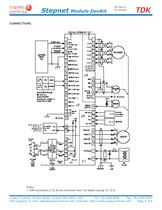
Stepnet Module DevKit For Rev 4 PC boards TDK CONNECTIONS Notes: 1. CAN connectors J7 & J8 are not shown here. For details see pp. 2,7, & 8. Copley Controls, 20 Dan Road, Canton, MA 02021, USA Tel: 781-828-8090 Fax: 781-828-6547 Tech Support: E-mail: [email protected], Internet: http://www.copleycontrols.com Page 5 of 8
Open the catalog to page 5
Stepnet Module DevKit For Rev 4 PC boards CONNECTOR LAYOUT TDK CANopen Signal Pin (Reserved) 1 CAN_L 2 CAN_GND 4 (CAN_SHLD) J8 SIGNAL 3 (Reserved) 5 J7 PIN +5V Input 1 Gnd 2 Gnd 3 Aux HV 4 J1 SIGNAL +HV Input J8 PIN J1 1 GND 2 Motor A+ Output 3 Motor A- Output 4 Motor B+ Output 5 Motor B- Output 6 J2 PIN J2 SIGNAL PIN Encoder /A Input 15 Encoder /B Input 14 Encoder /X Input 13 Signal Ground 12 +5V Output 11 Signal Ground 10 Motor Temp Sensor [IN5] 9 8 7 6 5 4 3 2 1 J2 SIGNAL Encoder A Input Encoder B Input Encoder X Input Signal Ground N.C. N.C. N.C. Chassis Ground Copley Controls, 20 Dan Road,...
Open the catalog to page 6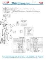
For Rev 4 PC boards Stepnet Module DevKit Pin 6 CANopen Signal CAN_GND 7 CAN_H 8 (Reserved) 9 (CAN_V+) TDK CANopen Notes: 1. Connector pinouts for J6 & J7 follow CAN standard DS-102. 2. Signals in ( ) are wired-through from J7 to J6 and have no other connections on the pc board. 3. CAN_GND is connected to Gnd on pc board (Stepnet signal and power ground) J6 PIN 1 J5 SIGNAL - 2 J5 + 3 F PIN 6 J4 J4 SIGNAL No Connection 5 TxD Output 4 Ground 3 J3 SIGNAL PIN Chassis Ground 1 Motemp [IN5] 2 GP Input [IN6] 3 GP Input [IN4] 4 Enable Input [IN1] 5 Output [OUT2] 6 HS Input [IN11] 7 HS Input [IN9] 8 HS...
Open the catalog to page 7
Stepnet Module DevKit For Rev 4 PC boards TDK ORDERING GUIDE PART NUMBER TDK-075-01 DESCRIPTION Stepnet™ Development Kit TDK-CK Stepnet™ Development Kit Connector Kit SER-CK Serial Cable Kit CME2 CME 2™ Drive Configuration Software CD-ROM Note: Specifications subject to change without notice Version 3.01_tu 11/29/2011 Copley Controls, 20 Dan Road, Canton, MA 02021, USA Tel: 781-828-8090 Fax: 781-828-6547 Tech Support: E-mail: [email protected], Internet: http://www.copleycontrols.com Page 8 of 8
Open the catalog to page 8All Copley Controls catalogs and technical brochures
 XenusPLUS Compact EtherCAT XEC
30 Pages
 XenusPLUS Compact CANopen XPC
30 Pages
 Control Networks
8 Pages
 R-Series Guide
8 Pages
 Selection Guide
24 Pages
 Xenus R10
30 Pages
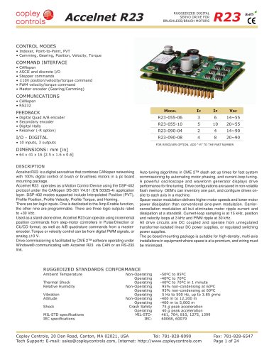 Accelnet R23
24 Pages
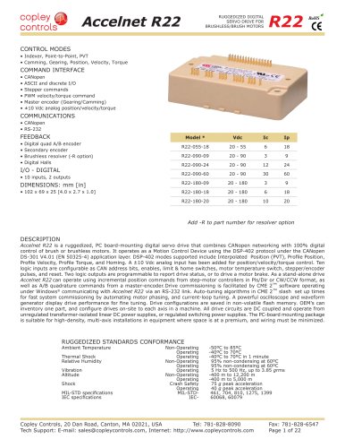 Accelnet R22
22 Pages
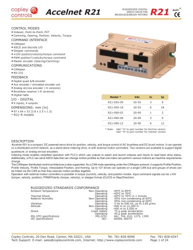 Accelnet R21
24 Pages
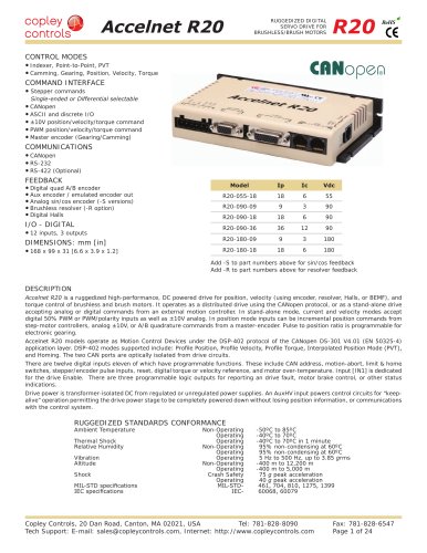 Accelnet R20
24 Pages
 Accelus Card Development Kit
6 Pages
 Accelus Card
8 Pages
 ASP-X2 Accelus Panel Dual
10 Pages
 Junus
Junus10 Pages
 CAN-PCI-02
2 Pages
 CAN-IPM-01
8 Pages
 Bantam
18 Pages
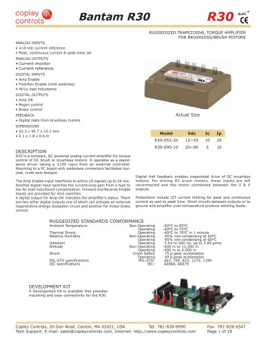 Bantam R30
18 Pages
 503
5036 Pages
 Power Supply Subsystem
8 Pages
 Shunt Regulator
2 Pages
 Xenus PLUS 2-Axis CANopen
34 Pages
 Xenus RoHS PLUS CANopen
28 Pages
 Xenus PLUS 2-Axis EtherCAT
34 Pages
 Xenus PLUS EtherCAT
28 Pages
 Xenus Edge Filter
16 Pages
 Regen Resistors
24 Pages
 Xenus Micro
24 Pages
 Accelus Card Development Kit
6 Pages
 Accelus Card
8 Pages
 Accelus Panel
10 Pages
 Xenus XTL
30 Pages
 Accelnet Plus EtherCAT Panel
18 Pages
 Accelnet Micro Module and Kit
24 Pages
 Accelnet Micro Panel
24 Pages
 Accelnet Module Development Kit
8 Pages
 Accelnet Module
14 Pages
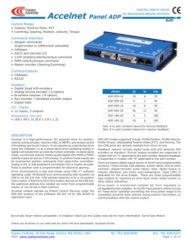 Accelnet Panel ADP
24 Pages


- Digital I/O
- Analog I/O
- Servo-amplifier
- Motor controller
- DC servo-amplifier
- Fieldbus servo-drive
- DC motor controller
- Stepper motor controller
- AC servo-amplifier
- Communication interface card
- Brushless servo drive
- Compact servo-amplifier
- EtherCAT servo-amplifier
- Digital servo-amplifier
- Industrial interface expansion card
- CANopen servo-amplifier
- CANopen I/O
- Brushless motor control
- Digital input motor controller
- I/O card