Catalog excerpts
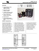
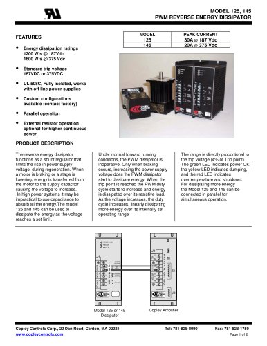
MODEL 125, 145 PWM REVERSE ENERGY DISSIPATOR MODEL • • • • • • Energy dissipation ratings 1200 W·s @ 187Vdc 1600 W·s @ 375 Vdc PEAK CURRENT 125 145 FEATURES 30A @ 187 Vdc 20A @ 375 Vdc Standard trip voltage 187VDC or 375VDC UL 508C, Fully isolated, works with off line power supplies Custom configurations available (contact factory) Parallel operation External resistor operation optional for higher continuous power PRODUCT DESCRIPTION The reverse energy dissipator functions as a shunt regulator that limits the rise in power supply voltage, during regeneration. When a motor is braking or a stage is lowering, energy is transferred from the motor to the supply capacitor causing the voltage to increase. In high power systems it may be impractical to use capacitance to absorb all the energy.The model 125 and 145 can be used to dissipate the energy as the voltage reaches a set limit. Under normal forward running conditions, the PWM dissipator is inoperative. Only when braking occurs, increasing the power supply voltage does the PWM dissipator start to dissipate energy. When the trip point is reached the PWM duty cycle starts to increase and energy is dissipated over its resistive load. As the voltage increases, the duty cycle increases, linearly dissipating more energy over its internally set operating range The range is directly proportional to the trip voltage (4% of Trip point). The green LED indicates power OK, the yellow LED indicates dumping, and the red LED indicates overtemperature and shutdown. For dissipating more energy the Model 125 and 145 can be connected in parallel for simultaneous operation. POWER OK REGEN FAULT J1 + - FRAME GROUND DC INPUT EXTERNAL REGEN RESISTOR STATUS + MOTOR + H N BUSS - 1 2 3 4 5 6 7 + BUSS R EXT STATUS + AC J1 U V W 1 2 3 4 5 6 7 8 9 J3 J2 Model 125 or 145 Dissipator Copley Controls Corp., 20 Dan Road, Canton, MA 02021 www.copleycontrols.com Copley Amplifier Tel: 781-828-8090 Fax: 781-828-1750 Page 1 of 2
Open the catalog to page 1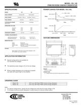
MODEL 125, 145 PWM REVERSE ENERGY DISSIPATOR SPECIFICATIONS POWER CURVES FOR MODEL 145 (125) MODEL 125 145 30A @ 200V 20A @ 400V PEAK POWER 6k Watts * 200 ms 8k Watts * 200 ms PEAK ENERGY 1200 W·s 1600 W·s CONTINUOUS POWER (See note 2) 120 Watts 160 Watts V >= 390V (195V) PEAK CURRENT 8k W (6k W) Typical V < 390V (195V) Watts 160 W (120 W) 0.2 s 20A (30A) OPERATING VOLTAGE Trip point Range Stability >10 s Time 187V 7.5V 0.2% 375V 15V 0.2% < 30 mA < 30 mA Amps 0.4A (0.6A) QUIESCENT CURRENT 375V (187V) THERMAL REQUIREMENTS operating temperature Storage temperature 400V (200V) Volts 0°C to 70°...
Open the catalog to page 2All Copley Controls catalogs and technical brochures
-
XenusPLUS Compact EtherCAT XEC
30 Pages
-
XenusPLUS Compact CANopen XPC
30 Pages
-
Control Networks
8 Pages
-
R-Series Guide
8 Pages
-
Selection Guide
24 Pages
-
Xenus R10
30 Pages
-
Accelnet R23
24 Pages
-
Accelnet R22
22 Pages
-
Accelnet R21
24 Pages
-
Accelnet R20
24 Pages
-
Accelus Card Development Kit
6 Pages
-
Accelus Card
8 Pages
-
ASP-X2 Accelus Panel Dual
10 Pages
-
Junus
10 Pages
-
CAN-PCI-02
2 Pages
-
CAN-IPM-01
8 Pages
-
Bantam
18 Pages
-
Bantam R30
18 Pages
-
503
6 Pages
-
Power Supply Subsystem
8 Pages
-
Xenus PLUS 2-Axis CANopen
34 Pages
-
Xenus RoHS PLUS CANopen
28 Pages
-
Xenus PLUS 2-Axis EtherCAT
34 Pages
-
Xenus PLUS EtherCAT
28 Pages
-
Xenus Edge Filter
16 Pages
-
Regen Resistors
24 Pages
-
Xenus Micro
24 Pages
-
Accelus Card Development Kit
6 Pages
-
Accelus Card
8 Pages
-
Accelus Panel
10 Pages
-
Xenus XTL
30 Pages
-
Accelnet Plus EtherCAT Panel
18 Pages
-
Accelnet Micro Module and Kit
24 Pages
-
Accelnet Micro Panel
24 Pages
-
Accelnet Module Development Kit
8 Pages
-
Accelnet Module
14 Pages
-
Accelnet Panel ADP
24 Pages

