- Catalogs
- Copley Controls
- Regen Resistors
Regen Resistors

Regen Resistors
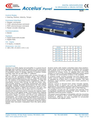
This guide provides comprehensive instructions for selecting, installing, and configuring external regeneration resistors for Xenus Amplifiers. It references additional documentation like the Xenus User Guide and CME 2 User Guide available online.
Users must follow safety regulations and only allow Copley Controls Corporation to repair amplifiers. The guide warns of hazardous voltages and electric shock risks, stressing the importance of operating within specified limits.
- Regen Resistor Theory: Describes the regeneration process where electrical energy is converted to mechanical energy and vice versa, managing excess energy during deceleration by shunting it into an external resistor to prevent over-voltage shutdown.
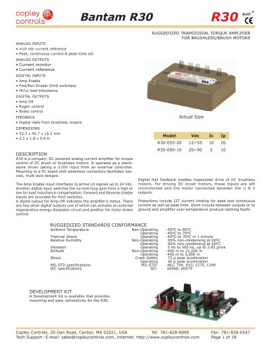
- Amplifier Regen Circuit Output Specifications: Provides specifications for different models, including continuous and peak power, minimum resistance, and turn-on/off voltages.
- Copley Standard Regen Resistors: Details standard resistors provided by Copley Controls, including dimensions, specifications, and thermal characteristics, warning against setting continuous power above default values due to high-temperature risks.
- Regen Circuit Wiring: Offers wiring instructions for regen resistors, emphasizing compliance with electrical codes and the dangers of improper grounding.
Outlines steps for sizing and configuring regen resistors, including gathering necessary information, calculating energy and power requirements, and selecting appropriate fuses. It also guides configuring custom regen resistors.
The guide ensures safe and efficient operation of regen resistors with Xenus amplifiers, emphasizing adherence to safety standards and proper configuration to prevent equipment damage or personal injury.
The Xenus Regeneration Guide by Copley Controls Corporation focuses on sizing and configuring regeneration resistors for amplifiers, providing detailed procedures and formulas for various motor applications.
Outlines steps to configure a regen resistor using CME 2 software, allowing users to select standard or custom resistors. Configurations can be saved to flash memory or canceled to revert to previous settings.
- Sizing a Regen Resistor: Provides a step-by-step approach to gather necessary motor and amplifier information, calculate energy returned during deceleration, and determine the need for a regen resistor.
- Formulas: Offers detailed formulas for calculating energy returned, energy dissipated by the motor, and energy returned to the amplifier, assessing if the energy exceeds the amplifier's capacity.
- Regen Resistor Requirements: Explains how to calculate the energy to be dissipated by the regen resistor and the necessary resistance value if energy exceeds the amplifier's capacity.
- Fuse Selection: Provides guidelines for selecting appropriate fuses based on peak and continuous current ratings.
Instructions for configuring a custom regen resistor, emphasizing the importance of entering correct values to prevent damage. The process involves entering resistance, continuous power, and peak power values, followed by a review and saving of the configuration.
The guide concludes with a warning about potential equipment damage if incorrect values are entered during configuration, stressing the importance of following procedures accurately.
Catalog excerpts

Xenus™ Regeneration Guide P/N 95-00306-000 Revision 3 June 2008
Open the catalog to page 1
Xenus Regeneration Guide This page for notes.
Open the catalog to page 2
Table of Contents Xenus Regeneration Guide ii Copley Controls Corp. This page for notes.
Open the catalog to page 4
Copley Controls Corp. iii ABOUT THIS GUIDE Overview and Scope This guide describes the selection, installation, and configuration of external regen resistors for Xenus Amplifiers. Related Documentation Users should also read these Copley Controls documents: • Xenus User Guide • CME 2 User Guide Links to these publications, along with hardware manuals and data sheets, can be found under the Documents heading of http://www.copleycontrols.com/Motion/Downloads/index.html. Information on Copley Controls Software can be found at: http://www.copleycontrols.com/Motion/Products/Software/index.html Comments...
Open the catalog to page 5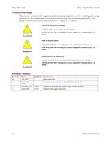
About this Guide Xenus Regeneration Guide iv Copley Controls Corp. Product Warnings Observe all relevant state, regional, and local safety regulations when installing and using this product. For safety and to assure compliance with documented system data, only Copley Controls Corporation should perform repairs to amplifiers. DANGER: Hazardous voltages. ! DANGER Exercise caution when installing and adjusting. Failure to heed this warning can cause equipment damage, injury, or death. Risk of electric shock. ! DANGER High-voltage circuits on J1, J2, and J3 are connected to mains power. Failure to...
Open the catalog to page 6
Regen Resistor Sizing and Configuration Xenus Regeneration Guide 2 Copley Controls Corp. 1.1: Regen Resistor Theory When a load is accelerated electrical energy is converted into mechanical energy. During deceleration the conversion is reversed. This is called regeneration. Some of this regenerated energy is lost to friction in the mechanical system. More of this energy is converted to heat due to I2R losses in the motor windings, cabling and drive electronics. The remainder of the energy is added to the electrical energy already stored in the internal capacitor bank of the amplifier. The result...
Open the catalog to page 8
Xenus Regeneration Guide Regen Resistor Sizing and Configuration Copley Controls Corp. 3 1.2: Amplifier Regen Circuit Output Specifications This section describes the amplifier’s regen resistor circuit output specifications. Model XTL-230-18 XTL-230-36 XTL-230-40 Continuous Power 2 kW 4 kW Peak Power 5 kW 10 kW Minimum Resistance 30 15 Minimum Resistor Wattage 25 W 50 W Turn On Voltage +390 Vdc Turn Off Voltage +380 Vdc DC Bus Capacitance 1760 ìF nominal Regen Energy Absorption Capacity Input Voltage 120 Vac 208 Vac 240 Vac 108 joules 57 joules 32 joules
Open the catalog to page 9
Regen Resistor Sizing and Configuration Xenus Regeneration Guide 4 Copley Controls Corp. 1.3: Copley Standard Regen Resistors Copley Controls provides two standard regen resistors for Xenus amplifiers: XTL-RA-03 and XTL-RA-04. XTL-RA-03 and XTL-RA-04 housing is shown below. 1.3.1: Copley Standard Regen Resistor Dimensions The diagram below shows XTL-RA-03 and XTL-RA-04 mounting dimensions (in mm).
Open the catalog to page 10
Xenus Regeneration Guide Regen Resistor Sizing and Configuration Copley Controls Corp. 5 1.3.2: Copley Standard Regen Resistor Specifications Specifications for Copley’s standard regen resistors are described below. Model Resistance Default Continuous Power Max Continuous Power Peak Power Peak Power Time For Use With XTL-RA-03 30 ohms 65 W 400 W 5 kW 1000 ms XTL-230-18 XTL-RA-04 15 ohms 65 W 400 W 10 kW 1000 ms XTL-230-36 XTL-230-40 High Temperature Risk. ! WARNING Setting Default Continuous Power for a standard Copley regen resistor to a value greater than the default of 65 W may cause the resistor...
Open the catalog to page 11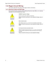
Regen Resistor Sizing and Configuration Xenus Regeneration Guide 6 Copley Controls Corp. 1.4: Regen Circuit Wiring This section describes the wiring of the regen resistor connections. 1.4.1: Electrical Codes and Warnings Be sure that all wiring complies with the National Electrical Code (NEC) or its national equivalent, and all prevailing local codes. DANGER: Hazardous voltages. ! DANGER Exercise caution when installing and adjusting. Failure to heed this warning can cause equipment damage, injury, or death. Risk of electric shock. ! DANGER High-voltage circuits on J1, J2, and J3 are connected...
Open the catalog to page 12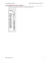
Xenus Regeneration Guide Regen Resistor Sizing and Configuration Copley Controls Corp. 7 1.4.2: Amplifier Connector Locations Connector locations are shown below. The regen connector is J3. CNTRL J4 J3 J2 J1 STATUS RS232 CAN ADDR J5 S1 J6 J7 J8 FDBCK +24V BRAKE RTN REGEN+ UVW L1 L2 L3 CAN Xenus™ REGENFDBCK +24V BRAKE RTN
Open the catalog to page 13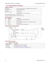
Regen Resistor Sizing and Configuration Xenus Regeneration Guide 8 Copley Controls Corp. 1.4.3: Regen Resistor (J3) Wiring Mating Connector Description Euro-style, 5 position, 5.0 mm pluggable male terminal block. Manufacturer PN Wago 721-605/000-043 Wire Size 22 - 14 AWG Recommended Wire 14 AWG, 600 V (Shielded cable used for CE compliance) Wire Insertion/Extraction Tool Wago 231-131 Connector and tool are included in connector kit XTL-CK Pin Description Pin Signal Function 1 Regen + + DC Bus to one side of regen resistor 2 N/C No connection 3 Regen - Collector of regen transistor to one side...
Open the catalog to page 14
Xenus Regeneration Guide Regen Resistor Sizing and Configuration Copley Controls Corp. 9 1.4.4: Regen Resistor Configuration with CME 2 1.4.4.1 Click Configure Regen ( ) to open the Regen Resistor screen. 1.4.4.2 Select a resistor option. Option Description None No external regen resistor is used. XTL-RA-03 XTL-RA-04 Standard regen resistors supplied by Copley Controls. Custom Resistor User-supplied resistor. See Regen Resistor Sizing and Configuration (p. 11). 1.4.4.3 Click OK to save regen settings to flash memory and close the Regen Resistor screen OR click Cancel to restore to previous values...
Open the catalog to page 15
Regen Resistor Sizing and Configuration Xenus Regeneration Guide 10 Copley Controls Corp. This page for notes.
Open the catalog to page 16
Regen Resistor Sizing and Configuration Xenus Regeneration Guide 12 Copley Controls Corp. A.1: Sizing a Regen Resistor A.1.1: Gather Required Information Calculating the power and resistance of the regen resistor requires information about the amplifier and the rotary or linear motor application. A.1.1.1 For all applications, gather the following information: 1 Details of the complete motion profile, including times and velocities 2 Amplifier model number 3 Applied line voltage to the amplifier 4 Torque constant of the motor 5 Resistance (line-to-line) of the motor windings. A.1.1.2 For rotary...
Open the catalog to page 18All Copley Controls catalogs and technical brochures
 XenusPLUS Compact EtherCAT XEC
30 Pages
 XenusPLUS Compact CANopen XPC
30 Pages
 Control Networks
8 Pages
 R-Series Guide
8 Pages
 Selection Guide
24 Pages
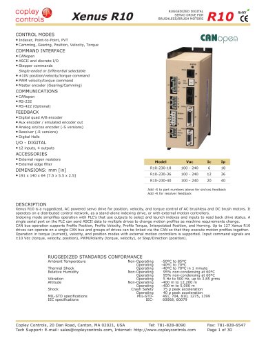 Xenus R10
30 Pages
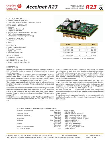 Accelnet R23
24 Pages
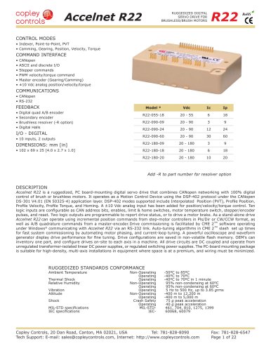 Accelnet R22
22 Pages
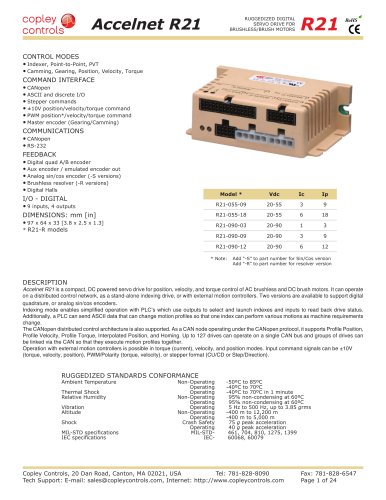 Accelnet R21
24 Pages
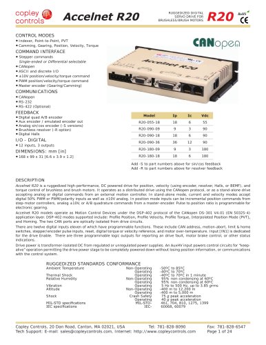 Accelnet R20
24 Pages
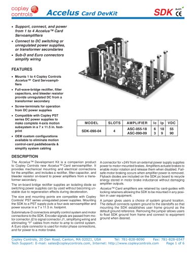 Accelus Card Development Kit
6 Pages
 Accelus Card
8 Pages
 ASP-X2 Accelus Panel Dual
10 Pages
 Junus
Junus10 Pages
 CAN-PCI-02
2 Pages
 CAN-IPM-01
8 Pages
 Bantam
18 Pages
 Bantam R30
18 Pages
 503
5036 Pages
 Power Supply Subsystem
8 Pages
 Shunt Regulator
2 Pages
 Xenus PLUS 2-Axis CANopen
34 Pages
 Xenus RoHS PLUS CANopen
28 Pages
 Xenus PLUS 2-Axis EtherCAT
34 Pages
 Xenus PLUS EtherCAT
28 Pages
 Xenus Edge Filter
16 Pages
 Xenus Micro
24 Pages
 Accelus Card Development Kit
6 Pages
 Accelus Card
8 Pages
 Accelus Panel
10 Pages
 Xenus XTL
30 Pages
 Accelnet Plus EtherCAT Panel
18 Pages
 Accelnet Micro Module and Kit
24 Pages
 Accelnet Micro Panel
24 Pages
 Accelnet Module Development Kit
8 Pages
 Accelnet Module
14 Pages
 Accelnet Panel ADP
24 Pages


- Digital I/O
- Analog I/O
- Servo-amplifier
- Motor controller
- DC servo-amplifier
- Fieldbus servo-drive
- DC motor controller
- Stepper motor controller
- AC servo-amplifier
- Communication interface card
- Brushless servo drive
- Compact servo-amplifier
- EtherCAT servo-amplifier
- Digital servo-amplifier
- Industrial interface expansion card
- CANopen servo-amplifier
- CANopen I/O
- Brushless motor control
- Digital input motor controller
- I/O card