Junus
1 /10Pages

Junus
1 /10Pages
Catalog excerpts
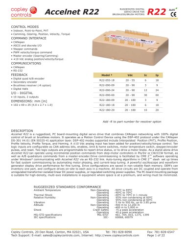
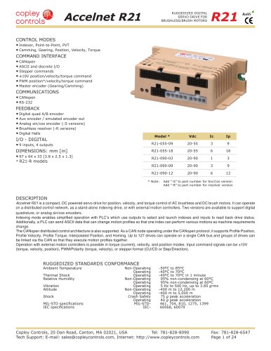
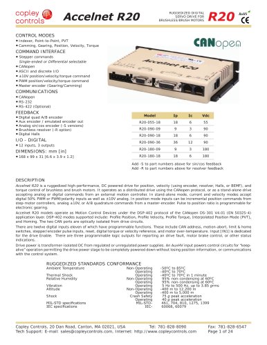
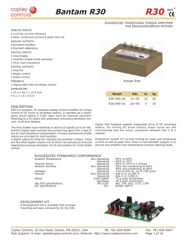
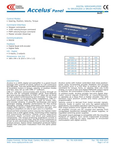
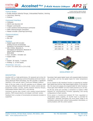
Junus DIGITAL SERVOAMPLIFIER for DC BRUSH MOTORS JSP RoHS Control Modes • Velocity, Torque Command Interface • ±10V velocity/torque command • PWM velocity/torque command Communications • RS232 Feedback • Back-EMF (velocity mode) I/O - Digital • 5 inputs, 1 output Dimensions: mm [in] • 130 x 82 x 31 [5.1 x 3.2 x 1.2] MODEL Ic Ip Vdc JSP-090-10 5 10 90 JSP-090-20 10 20 90 JSP-180-10 5 10 180 JSP-180-20 10 20 180 JSP-180-30 15 30 180 DESCRIPTION The Junus™ digital servoamplifier puts 100% digital control of DC brush motors in a panel-mounting package with power options to ±15 Adc continuous and ±30 Adc peak from +20 Vdc to +180 Vdc DC power supplies. Torque mode operation works with popular position-loop controllers that use PID filters to close a position-loop. Sensorless velocity control works with position loop controllers that only output a position-error signal such as PLC’s. Set-up is fast and automated by CME 2™ software operating under Windows®. CME 2™ communicates with Junus™ through an RS-232 link for complete amplifier setup. Auto-tuning algorithms in CME 2™ slash set up times for fast system commissioning by automating current and velocity-loop tuning. A powerful oscilloscope and signal generator display amplifier performance for fine tuning thereafter. Amplifier control parameters are saved in non-volatile flash memory. OEM’s can inventory one part, and configure amplifiers on-site to each axis in a machine. Current-loop sampling at 20 kHz yields high-bandwidth with full adjustability. The velocity loop is sampled at 4 kHz for wide velocity bandwidths. Carrier-cancellation modulation all but eliminates motor ripple current and dissipation at a standstill, and provides excellent crossover characteristics for voice-coil applications that demand low distortion around zero. PWM ripple is at 40 kHz, further minimizing losses in low-inductance motors. Sensorless velocity control regulates motor back-EMF and compensates for changes in load that would cause a speed change with simple voltage controls. Amplifier output voltage is increased to offset the internal I*R voltage drops, keeping back-emf constant. All amplifier circuits are DC coupled and operate from unregulated transformer-isolated DC power supplies, or regulated switching power supplies. The panel-mount package is compatible with the mounting footprint of Copley’s 4xx series analog DC brush-motor amplifiers, offering an easy upgrade to 100% digital control. Copley Controls, 20 Dan Road, Canton, MA 02021, USA Tel: 781-828-8090 Tech Support: E-mail: [email protected], Internet: http://www.copleycontrols.com Fax: 781-828-6547 Page 1 of 10
Open the catalog to page 1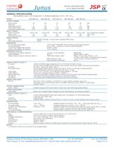
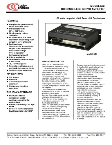
Junus JSP DIGITAL SERVOAMPLIFIER for DC BRUSH MOTORS RoHS GENERAL SPECIFICATIONS Test conditions: Load = 1mH in series with 1 Ω. Ambient temperature = 25 °C. +HV = HVmax MODEL OUTPUT POWER JSP-090-10 JSP-090-20 JSP-180-10 10 1 5 0.85 0.43 20 1 10 1.64 0.85 10 1 5 1.73 0.87 +20 to +90 10 4.53 +20 to +90 20 9.07 +20 to +180 10 4.53 Peak Current Peak time Continuous current Peak Output Power Continuous Output Power INPUT POWER HVmin to HVmax Peak current Continuous current PWM OUTPUTS Type PWM ripple frequency JSP-180-20 20 1 10 3.41 1.73 Current loop, small signal HV Compensation Current loop update...
Open the catalog to page 2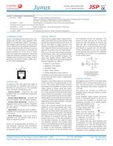
Junus DIGITAL SERVOAMPLIFIER for DC BRUSH MOTORS JSP RoHS AGENCY STANDARDS CONFORMANCE EN 55011 : 1998 CISPR 11 (1997) Edition 2/Amendment 2: Limits and Methods of Measurement of Radio Disturbance Characteristics of Industrial, Scientific, and Medical (ISM) Radio Frequency Equipment EN 50082-1 : 1997 Electromagnetic Compatibility Generic Immunity Requirements Following the provisions of EC Directive 89/336/EEC: EN 60204-1 : 1997 Safety of Machinery - Electrical Equipment of Machines Following the provisions of EC Directive 98/37/EC: UL 508C : 1996 UL Standard for Safety for Power Conversion Equipment...
Open the catalog to page 3
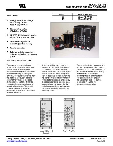
Junus JSP DIGITAL SERVOAMPLIFIER for DC BRUSH MOTORS REFERENCE INPUTS DIGITAL REFERENCE INPUTS The Reference inputs command the amplifier to produce an output. Junus™ has analog and digital reference inputs. Only one can be active at a time. [IN4] and [IN5] are logic inputs for digital reference signals that are programmable for controlling torque or velocity. If they are not used as reference inputs they can be programmed with the same functions as [IN2] & [IN3]. The electrical structure of these inputs is shown below: RoHS The analog input takes a ±10 Vdc signal, and the digital input(s) take...
Open the catalog to page 4
Junus DIGITAL SERVOAMPLIFIER for DC BRUSH MOTORS GROUNDING CONSIDERATIONS All of the circuits in Junus™ share a common circuit-ground (Ground on J1-3, 4 and Signal Ground on J2-7,10,11,12, and J3-3 & 4). Input logic circuits are referenced to Signal Ground, as are analog reference inputs, and the digital output. For this reason, amplifier Gnd terminals should connect to the users’ common ground system so that signals between amplifier and controller are at the same common potential, and to minimize noise. The system ground should, in turn, connect to an earthing conductor at some point so that...
Open the catalog to page 5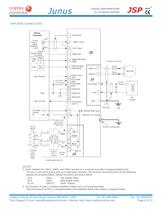
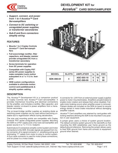
Torque & Velocity LIMIT SWITCHES signals canned Ref(+) Input Digital Polarity Enable Input Fault Output Amplifier mounting screw Serial Cable Kit SER-CK 3. The function of [INI] is always Amplifier Enable and is not programmable. The active level of [INI] is programmable, and amplifier Reset with enable is programmable.
Open the catalog to page 6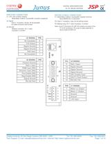
Junus DIGITAL SERVOAMPLIFIER for DC BRUSH MOTORS JSP AMPLIFIER CONNECTORS MATING (CABLE) CONNECTORS J1: +HV, Gnd, & Motor Outputs Molex/Beau 5,08mm, Eurostyle®, 5-position receptacle P1: Molex/Beau 5,08mm, Eurostyle®, 5-position terminal block 860505-00, or equivalent J2: Signal: Sub-D, 15-position, female, #4-40 standoffs for cable-connector shell screws P2: Sub-D, 15-position, male, #4-40 locking screws J3: RS-232: Modular connector, RJ-11 style 6-position, 4-contact RoHS Note: Junus™ Connector Kit JSP-CK contains one each of the P1 & P2 connectors. P3 is part of cable assembly in Serial Cable...
Open the catalog to page 7All Copley Controls catalogs and technical brochures
 XenusPLUS Compact EtherCAT XEC
30 Pages
 XenusPLUS Compact CANopen XPC
30 Pages
 Control Networks
8 Pages
 R-Series Guide
8 Pages
 Selection Guide
24 Pages
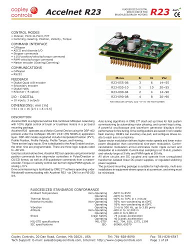
 Xenus R10
30 Pages
 Accelnet R23
24 Pages
 Accelnet R22
22 Pages
 Accelnet R21
24 Pages
 Accelnet R20
24 Pages
 Accelus Card Development Kit
6 Pages
 Accelus Card
8 Pages
 ASP-X2 Accelus Panel Dual
10 Pages
 CAN-PCI-02
2 Pages
 CAN-IPM-01
8 Pages
 Bantam
18 Pages
 Bantam R30
18 Pages
 503
5036 Pages
 Power Supply Subsystem
8 Pages
 Shunt Regulator
2 Pages
 Xenus PLUS 2-Axis CANopen
34 Pages
 Xenus RoHS PLUS CANopen
28 Pages
 Xenus PLUS 2-Axis EtherCAT
34 Pages
 Xenus PLUS EtherCAT
28 Pages
 Xenus Edge Filter
16 Pages
 Regen Resistors
24 Pages
 Xenus Micro
24 Pages
 Accelus Card Development Kit
6 Pages
 Accelus Card
8 Pages
 Accelus Panel
10 Pages
 Xenus XTL
30 Pages
 Accelnet Plus EtherCAT Panel
18 Pages
 Accelnet Micro Module and Kit
24 Pages
 Accelnet Micro Panel
24 Pages
 Accelnet Module Development Kit
8 Pages
 Accelnet Module
14 Pages
 Accelnet Panel ADP
24 Pages


- Digital I/O
- Analog I/O
- Servo-amplifier
- Motor controller
- DC servo-amplifier
- Fieldbus servo-drive
- DC motor controller
- Stepper motor controller
- AC servo-amplifier
- Communication interface card
- Brushless servo drive
- Compact servo-amplifier
- EtherCAT servo-amplifier
- Digital servo-amplifier
- Industrial interface expansion card
- CANopen servo-amplifier
- CANopen I/O
- Brushless motor control
- Digital input motor controller
- I/O card