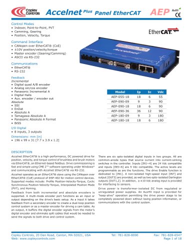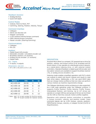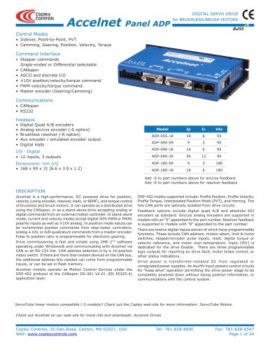
Catalog excerpts
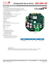
Integrated Servo Drive GENERAL SPECIFICATIONS Control Modes • • • • • Cyclic Synchronous Position-Velocity-Torque (CSP, CSV, CST) Cyclic Synchronous Torque with Commutation Angle (CSTCA) Profile Position-Velocity-Torque, Interpolated Position (PVT), Homing CVM: Indexer GUI, Programming Language CPL Camming, Gearing Command Interface • • • • CANopen application protocol over EtherCAT (CoE) ASCII and Serial Binary ±10 V Position/Velocity/Torque command Master encoder (Gearing/Camming) Communications • EtherCAT • Serial • Biss-C unidirectional, Absolute clock and data • SSI Port 2: Single-ended • Digital quad A/B/X • Digital U, V, W Digital high-speed input Analog motor overtemp input Analog differential input Digital brake output Digital buffer outputs Actual Size • 80 x 80 x 20 [2.5 x 1.6 x .65] mm [in] Center cutout diameter 10 [0.4] mm [in] Outer diameter 89.4 [3.52] mm [in] IES-060-30 is a single-board servo drive designed for mounting on motors or in robotic joints. A cutout in the center allows power and network cables to pass through. Copley Controls, 20 Dan Road, Suite 3, Canton, MA 02021, USA Tel: 781-828-8090 P/N 16-1207
Open the catalog to page 1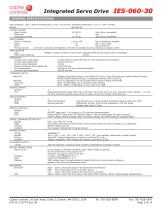
Integrated Servo Drive GENERAL SPECIFICATIONS Test conditions: Load = Wye connected load: 1 mH + 1Ω line-line. Ambient temperature = 25 °C. +HV = HVmax MODEL IES-060-30 OUTPUT POWER Peak Current Peak time Continuous current INPUT POWER HVmin to HVmax Ipeak Icont HV input power 30 (21.2) 1 15 (10.6) +14 to +60 30 15 2 W with no encoder and disabled, 6 W with no encoder and max PWM OUTPUTS Type PWM ripple frequency Adc (Arms, sinusoidal) Sec Adc (Arms, sinusoidal) Vdc, transformer-isolated Adc (1 sec) peak Adc continuous continuous output current MOSFET 3-phase inverter, 16 kHz...
Open the catalog to page 2
Integrated Servo Drive GENERAL SPECIFICATIONS FEEDBACK Absolute encoder: BiSS (B&C) Unidirectional SSI Incremental encoder: Quadrature A/B/X Digital Halls: Encoder power U, V, W: Single-ended, 120° electrical phase difference between U-V-W signals Schmitt trigger, 1 µs RC filter from active HI/LO sources, 24 Vdc compatible, 1.5 kΩ pull-up to +5 Vdc Vt+ = 2.5~3.5 Vdc, VT- = 1.3~2.2 Vdc, VH = 0.7~1.5 Vdc +5 Vdc ±2% @ 250 mAdc max, shared by dual encoders PROTECTIONS HV Overvoltage HV Undervoltage Drive over temperature Short circuits I2T Current limiting Latching / Non-Latching Motor...
Open the catalog to page 3
Integrated Servo Drive ETHERCAT COMMUNICATIONS EtherCAT is the open, real-time Ethernet network developed by Beckhoff based on the widely used 100BASE-TX cabling system. EtherCAT enables high-speed control of multiple axes while maintaining tight synchronization of clocks in the nodes. Data protocol is CANopen application protocol over EtherCAT (CoE) based on CiA 402 for motion control devices. More information on EtherCAT can be found on this web-site: http://ethercat.org/default.htm User Mounting board CME -> Basic Setup -> Operating Mode Options The table below shows the standard...
Open the catalog to page 4
Integrated Servo Drive MOTEMP INPUT The analog input [AIN1] Motemp, is for use with a motor overtemperature switch or sensor. The input voltage goes through a low-pass filter to a 12-bit A/D converter. The active level of the input, Vset, is programmable to generate an over-temperature fault if the MOTEMP voltage is Vset depending on the temperature coefficient of the sensor. MOTEMP Thermistor, Posistor, or switch MOTOR BRAKE OUTPUT A MOSFET with flyback diode drives a brake powered from +HV. The brake is driven from +HV which can be up to 60 Vdc. In order to drive brakes at their rated...
Open the catalog to page 5
Integrated Servo Drive HIGH SPEED INPUT: IN1 IN1 is programmable to a selection of functions. It has a 100 ns RC filter when driven by active sources (CMOS, TTL, etc) and a 10 kΩ pull-up resistor to +5 Vdc. In addition to the selection of functions, the active level is programmable. Input level functions have programmable HI or LO to activate the function. Input transition functions are programmable to activate on LO -> HI, or HI -> LO transitions. INPUT LEVEL FUNCTIONS • Drive Enable, Enable with Clear Faults, Enable with Reset • PWM Sync • Positive Limit Switch • Negative Limit Switch •...
Open the catalog to page 6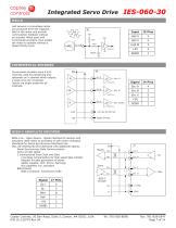
Integrated Servo Drive HALLS Hall sensors in a brushless motor are produced from the magnetic field in the motor and provide commutation feedback without an encoder. When used with incremental encoders, they enable the motor to operate without a phase-finding cycle. INCREMENTAL ENCODER Incremental encoders have A & B channels used for positioning and optionally an X channel which outputs a pulse once per revolution. Inputs are single-ended for all channels. BISS-C ABSOLUTE ENCODER BiSS is an - Open Source - digital interface for sensors and actuators. BiSS refers to principles of well known...
Open the catalog to page 7
Integrated Servo Drive SSI ABSOLUTE ENCODER The SSI (Synchronous Serial Interface) is an interface used to connect an absolute position encoder to a motion controller or control system. The IES drive provides a train of clock signals in differential format to the encoder which initiates the transmission of the position data on the subsequent clock pulses. The polling of the encoder data occurs at the current loop frequency (16 kHz). The number of encoder data bits and counts per motor revolution are programmable. The hardware bus consists of two signals: SCLK and SDATA. Data is sent in 8...
Open the catalog to page 8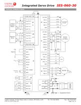
Integrated Servo Drive TYPICAL CONNECTIONS Control System Master REFIN+ REFINAGND Network Drive Absolute Encoder (Full duplex) Incremental Encoder Copley Controls, 20 Dan Road, Suite 3, Canton, MA 02021, USA Tel: 781-828-8090 P/N 16-120779 Rev 04
Open the catalog to page 9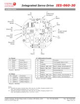
Integrated Servo Drive CONNECTORS J7 Differential Encoders J2 Motor J7: Differential Encoder Power Return Power Input Power Return Power Output Biss C /Data, Incremental /A Biss C Data, Incremental A Biss C /Clock, Incremental /X Biss C Clock, Incremental X Phoenix: 1823201 Notes J1: Contacts are push-in spring type. Wire size 24~16 AWG, stripping length 8 mm. Tool: slot-headed screwdriver 0.4 x 2.5 mm (~0.1”). J2: Contacts are push-in spring type. Wire size 24~12 AWG, stripping length 8 mm. Tool: slot-headed screwdriver 0.6 x 3.5 mm (~1/8”) Copley Controls, 20 Dan Road, Suite 3, Canton, MA...
Open the catalog to page 10All Copley Controls catalogs and technical brochures
-
XenusPLUS Compact EtherCAT XEC
30 Pages
-
XenusPLUS Compact CANopen XPC
30 Pages
-
Control Networks
8 Pages
-
R-Series Guide
8 Pages
-
Selection Guide
24 Pages
-
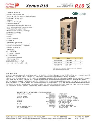
Xenus R10
30 Pages
-
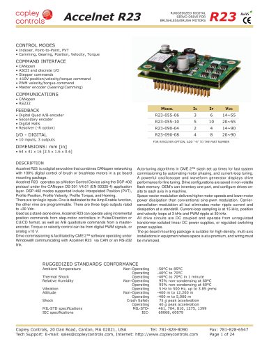
Accelnet R23
24 Pages
-
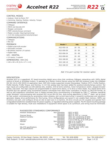
Accelnet R22
22 Pages
-
Accelnet R21
24 Pages
-
Accelnet R20
24 Pages
-
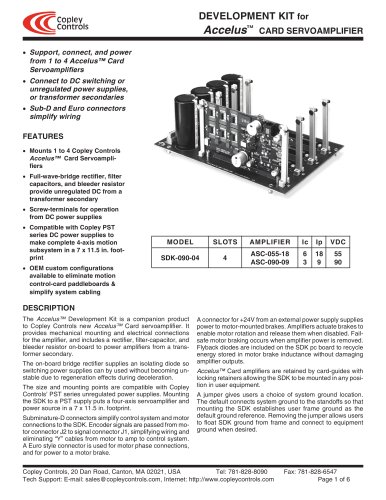
Accelus Card Development Kit
6 Pages
-
Accelus Card
8 Pages
-
ASP-X2 Accelus Panel Dual
10 Pages
-
Junus
10 Pages
-
CAN-PCI-02
2 Pages
-
CAN-IPM-01
8 Pages
-
Bantam
18 Pages
-
Bantam R30
18 Pages
-
503
6 Pages
-
Power Supply Subsystem
8 Pages
-
Shunt Regulator
2 Pages
-
Xenus PLUS 2-Axis CANopen
34 Pages
-
Xenus RoHS PLUS CANopen
28 Pages
-
Xenus PLUS 2-Axis EtherCAT
34 Pages
-
Xenus PLUS EtherCAT
28 Pages
-
Xenus Edge Filter
16 Pages
-
Regen Resistors
24 Pages
-
Xenus Micro
24 Pages
-
Accelus Card Development Kit
6 Pages
-
Accelus Card
8 Pages
-
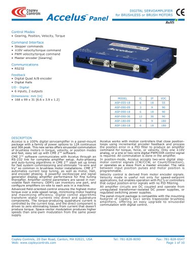
Accelus Panel
10 Pages
-
Xenus XTL
30 Pages
-
Accelnet Plus EtherCAT Panel
18 Pages
-
Accelnet Micro Module and Kit
24 Pages
-
Accelnet Micro Panel
24 Pages
-
Accelnet Module Development Kit
8 Pages
-
Accelnet Module
14 Pages
-
Accelnet Panel ADP
24 Pages


