
- Catalogs
- Copley Controls
- Bantam

- Products
- Catalogs
- News & Trends
- Exhibitions
Bantam

Bantam
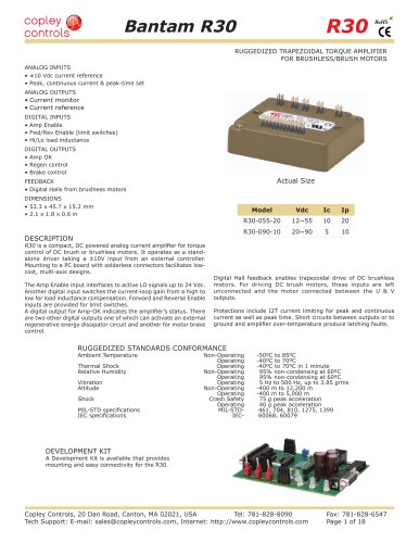
The Bantam RoHSBTM Trapezoidal Torque Amplifier Module is a compact, DC-powered analog current amplifier designed for torque control of DC brush or brushless motors. It functions as a stand-alone driver with a ±10V input from an external controller, suitable for low-cost, multi-axis designs.
- Models: BTM-055-20 and BTM-090-10 with different voltage and current specifications.
- Output Power: Includes peak and continuous current ratings with specific output power and resistance values.
- Input Power: Voltage range from +12 to +90 Vdc, transformer-isolated.
- PWM Outputs: 3-phase MOSFET, 33 kHz with trapezoidal commutation using digital Hall feedback.
- Feedback: Digital Halls for brushless motor commutation.
- Protections: Features I2T current limiting, short circuit, and over-temperature protections.
- Analog Inputs: ±10 Vdc current reference, peak, continuous current, and peak-time set.
- Digital Inputs: Amp Enable, Forward/Reverse Enable, and Hi/Lo load inductance.
- Digital Outputs: Amp OK, regenerative control, and brake control.
- Analog Outputs: Current monitor and reference monitor for current-loop command.
- Dimensions: 53.3 x 45.7 x 15.2 mm.
- Weight: Amplifier 0.082 lb, heatsink 0.113 lb.
- Operating Temperature: 0 to +45 °C, storage -40 to +85 °C.
- Humidity: 0 to 95%, non-condensing.
A development kit is available for easy mounting and connectivity.
Supports both brushless and brush motor connections with specific guidelines for Hall signals and phase connections.
Methods for setting peak and continuous current limits using voltage or resistors, with detailed examples and calculations.
Describes the use of PWM limiting to control the maximum RPM of a motor while operating in torque mode.
- The I2T limit for the BTM-055-20 amplifier is calculated as 300 A²·s. For different current limits, the new I2T is calculated as 63 A², resulting in a peak time of 4.76 seconds.
- To adjust the peak I2T time to 0.5 seconds, a new I2T limit of 54 A²·s is calculated. The ratio of the new I2T limit to the amplifier's I2T limit is 18%, suggesting the use of a 2.5k ohm resistor. Alternatively, a 2.2k ohm resistor can be used for precision.
- Voltage adjustment for the same effect is calculated as 0.90 Vdc.
- Install a low-ESR electrolytic capacitor within 12 inches of the drive to handle ripple currents effectively.
- Group P1 signals for current-sharing and follow IPC-2221 standards for conductor thickness and trace width.
- Minimize noise by routing power supply traces close together and keeping motor signal traces closely placed.
- Determine if a heatsink or fan-cooling is necessary by calculating the temperature rise and power dissipation.
- Use phase change material for optimal heat transfer when installing a heatsink.
- Charts provided help determine the need for additional cooling based on power dissipation and thermal resistance.
- The development kit includes various connectors and components for interfacing with the amplifier.
- Jumper settings on the development kit allow for configuration of balance, gain, and output signals.
- Ensure that the combined current from specific pins does not exceed 250 mA.
- JP2 and JP3 connectors are used to link various switches and terminals to the amplifier with specific functions such as enabling, disabling, and selecting gain.
- JP4 connectors are used for functions like I2T timing, current peak limit, and current continuous limit.
- The Bantam RoHSBTM Trapezoidal Torque Amplifier Module includes models BTM-055-20 and BTM-090-10, which are analog current amplifiers with different current ratings.
- A development kit (BDK-090-01) and a connector kit (BDK-CK) are available for these amplifiers.
- The connector kit includes various connectors and backshells, all compliant with RoHS standards.
- An optional heatsink kit (BTM-HK) is available for field installation, including thermal phase-change material and hardware.
- Copley Controls, located in Canton, MA, provides technical support via email and their website.
Catalog excerpts
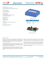
Bantam Trapezoidal Torque Amplifier Module BTM RoHS Analog Inputs • ±10 Vdc current reference • Peak, continuous current & peak-time set Analog Outputs • Current monitor • Current reference Digital Inputs • Amp Enable • Fwd/Rev Enable (limit switches) • Hi/Lo load inductance Digital Outputs • Amp OK • Regen control • Brake control Feedback • Digital Halls from brushless motors Dimensions • 53.3 x 45.7 x 15.2 mm • 2.1 x 1.8 x 0.6 in Actual Size Model Vdc Ic Ip BTM-055-20 12~55 10 20 BTM-090-10 20~90 5 10 DEVELOPMENT KIT DESCRIPTION Bantam is a compact, DC powered analog current amplifier for torque control of DC brush or brushless motors. It operates as a stand-alone driver taking a ±10V input from an external controller. Mounting to a PC board with solderless connectors facilitates lowcost, multi-axis designs. The Amp Enable input interfaces to active LO signals up to 24 Vdc. Another digital input switches the current-loop gain from a high to low for load inductance compensation. Forward and Reverse Enable inputs are provided for limit switches. Digital Hall feedback enables trapezoidal drive of DC brushless motors. For driving DC brush motors, these inputs are left unconnected and the motor connected between the U & V outputs. Protections include I2T current limiting for peak and continuous current as well as peak time. Short circuits between outputs or to ground and amplifier over-temperature produce latching faults. A Development Kit is available that provides mounting and easy connectivity for the Bantam. A digital output for Amp-OK indicates the amplifier’s status. There are two other digital outputs one of which can activate an external regenerative energy dissipator circuit and another for motor brake control. Copley Controls, 20 Dan Road, Canton, MA 02021, USA Tel: 781-828-8090 Tech Support: E-mail: [email protected], Internet: http://www.copleycontrols.com Fax: 781-828-6547 Page 1 of 18
Open the catalog to page 1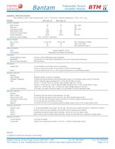
Bantam Trapezoidal Torque Amplifier Module BTM RoHS GENERAL SPECIFICATIONS Test conditions: Load = Wye connected load: 2 mH + 2 Ω line-line. Ambient temperature = 25°C, +HV = HVmax MODEL BTM-055-20 BTM-090-10 Peak Current Peak time Continuous current Peak Output Power Continuous Output Power Output resistance 20 1 10 1045 523 0.075 10 1 5 855 427 0.075 Maximum Output Voltage Vout = HV*0.97 - Rout*Iout OUTPUT POWER Adc, ±5% Sec Adc, ±5% W W Rout (Ω) INPUT POWER HVmin to HVmax Ipeak Icont +12 to +55 20 10 +20 to +90 10 5 Vdc, Transformer-isolated Adc (1 sec) peak Adc continuous (Note 1) PWM OUTPUTS...
Open the catalog to page 2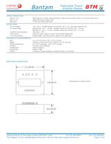
Bantam Trapezoidal Torque Amplifier Module BTM RoHS MOTOR CONNECTIONS Phase U, V, W Hall U, V, W Hall power PWM outputs to 3-phase ungrounded Wye or delta wound brushless motors, or DC brush motors (U-V) Digital Hall signals, single-ended +5 Vdc ±2% @ 250 mAdc max PROTECTIONS HV Overvoltage HV Undervoltage Amplifier over temperature Short circuits I2T Current limiting +HV > HVmax, Amplifier outputs turn off until +HV < HVmax (See Input Power for HV) BTM-090-10: +HV < +20 Vdc, Amplifier outputs turn off until +HV > +20 Vdc BTM-055-20: +HV < +12 Vdc, Amplifier outputs turn off until +HV > +12 Vdc...
Open the catalog to page 3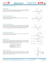
Bantam BTM Trapezoidal Torque Amplifier Module RoHS CONTROL INPUTS AND OUTPUTS ENABLE INPUT +5V The Enable input [IN1] is LO-active and pulled up to +5V by an internal 10k resistor. This provides fail-safe operation by disabling the amplifier if the Enable input is open, or a wire from the controller should break. 10k /Enable 74HC2G14 J1-18 10k 1nF FWD/REV ENABLE INPUTS +5V Two inputs are provided for limit switches. These should be LO for normal operation, and open or HI to inhibit current of positive or negative polarity. /PosEnab /NegEnab 10k J1-19 J1-20 74HC2G14 10k 1nF LOAD INDUCTANCE INPUT...
Open the catalog to page 4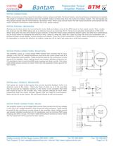
Bantam BTM Trapezoidal Torque Amplifier Module RoHS MOTOR CONNECTIONS Motor connections are of two types for brushless motors: phases and Halls. For brush motors, only the armature connections are needed. The phase or armature connections carry the amplifier output currents that drive the motor to produce motion. The Hall signals are three digital signals used for commutating a brushless motor. When using a brush motor the Hall inputs should be unconnected and the motor armature connections made between the U & V phase outputs. MOTOR PHASING: BRUSHLESS Phasing can be done simply by connecting...
Open the catalog to page 5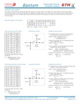
Bantam Trapezoidal Torque Amplifier Module BTM RoHS CURRENT LIMIT INPUTS Two inputs are provided for setting the peak and continuous current limits. The I-Peak and I-Cont inputs each have equivalent circuits shown below. Limits can be set either by applying a voltage (Vset) to the input or by connecting a resistor (Rset) between input and signal ground. The tables below show values for Rset and Vset that give 10~100% of the rated peak and continuous current ratings. AMPLIFIER MODELS AND RATINGS Model I-Peak I-Cont BTM-055-20 20 10 BTM-090-10 10 T-Peak 5 1 I2T 300 75 Note: I2T = (Ipeak2 - Icont2)...
Open the catalog to page 6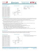
Bantam Trapezoidal Torque Amplifier Module BTM RoHS PWM LIMITING INPUT I2T LIMIT SETTINGS I2T LIMITS (AMP2·SECS) OF AMPLIFIERS EQUIVALENT CIRCUIT % Vi2t 100 5.0 90 4.50 90000 80 4.00 40000 70 3.50 23333 60 3.00 15000 50 2.50 10000 40 2.00 6667 30 1.50 4286 20 1.00 2500 10 0.50 I2T Limit = (Ipeak^2 - Icont^2) * 1 sec Ri2t 1111 Model I2T Limit BTM-055-20 300 BTM-090-10 75 +5 V 10000 J1-2 Vi2t I2T I2T Control Ri2t EXAMPLES OF I2T SETTINGS I2T Limit settings should be made after the peak and continuous current limits have been set. The time that the peak current can be maintained is then calculated...
Open the catalog to page 7
Bantam Trapezoidal Torque Amplifier Module BTM RoHS PC BOARD DESIGN Printed circuit board layouts for Bantam amplifiers should follow some simple rules: 1. Install a low-ESR electrolytic capacitor not more than 12 inches from the drive. PWM amplifiers produce ripple currents in their DC supply conductors. Bantam amplifiers do not use internal electrolytic capacitors as these can be easily supplied by the printed circuit board. In order to provide a good, low-impedance path for these currents a low-ESR capacitor should be mounted as close to the drive as possible. 330 µF is a minimum value, with...
Open the catalog to page 8All Copley Controls catalogs and technical brochures
 XenusPLUS Compact EtherCAT XEC
30 Pages
 XenusPLUS Compact CANopen XPC
30 Pages
 Control Networks
8 Pages
 R-Series Guide
8 Pages
 Selection Guide
24 Pages
 Xenus R10
30 Pages
 Accelnet R23
24 Pages
 Accelnet R22
22 Pages
 Accelnet R21
24 Pages
 Accelnet R20
24 Pages
 Accelus Card Development Kit
6 Pages
 Accelus Card
8 Pages
 ASP-X2 Accelus Panel Dual
10 Pages
 Junus
Junus10 Pages
 CAN-PCI-02
2 Pages
 CAN-IPM-01
8 Pages
 Bantam R30
18 Pages
 503
5036 Pages
 Power Supply Subsystem
8 Pages
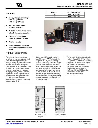 Shunt Regulator
2 Pages
 Xenus PLUS 2-Axis CANopen
34 Pages
 Xenus RoHS PLUS CANopen
28 Pages
 Xenus PLUS 2-Axis EtherCAT
34 Pages
 Xenus PLUS EtherCAT
28 Pages
 Xenus Edge Filter
16 Pages
 Regen Resistors
24 Pages
 Xenus Micro
24 Pages
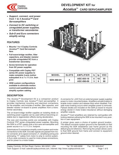 Accelus Card Development Kit
6 Pages
 Accelus Card
8 Pages
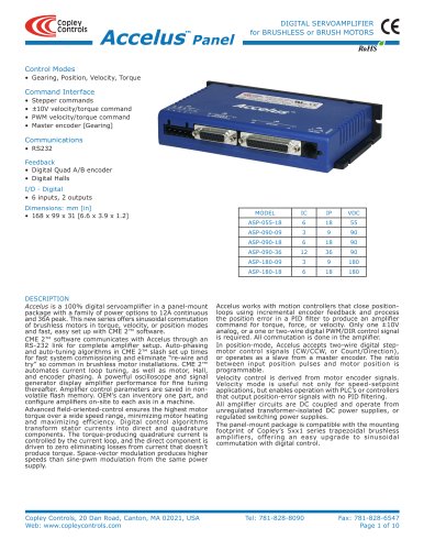 Accelus Panel
10 Pages
 Xenus XTL
30 Pages
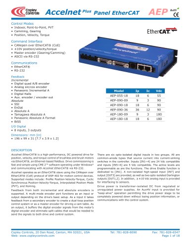 Accelnet Plus EtherCAT Panel
18 Pages
 Accelnet Micro Module and Kit
24 Pages
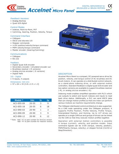 Accelnet Micro Panel
24 Pages
 Accelnet Module Development Kit
8 Pages
 Accelnet Module
14 Pages
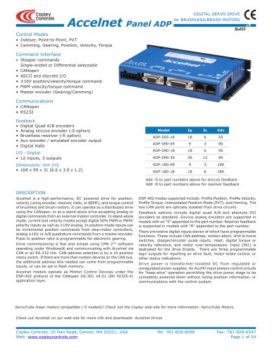 Accelnet Panel ADP
24 Pages


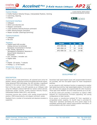
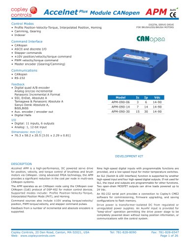



- Digital I/O
- Analog I/O
- Servo-amplifier
- Motor controller
- DC servo-amplifier
- Fieldbus servo-drive
- DC motor controller
- AC servo-amplifier
- Brushless servo-amplifier
- Stepper motor controller
- Communication interface card
- EtherCAT servo-amplifier
- Compact servo-amplifier
- CANopen servo-amplifier
- Digital servo-amplifier
- Stepper servo drive
- Industrial interface expansion card
- CANopen I/O
- Brushless motor control
- Digital input motor controller