Catalog excerpts
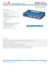
Accelus ASP-X2 Panel RoHS 2-AXIS DIGITAL SERVOAMPLIFIER for BRUSHLESS/BRUSH MOTORS Control Modes • Current (torque, force) Opto-Isolated Command Interface (per channel) • • • • ±10V Current control input Enable input Buffered encoder outputs A/B/X Digital outputs (4 total: programmable for use by either channel) Communications • RS-232 Feedback • Digital Quad A/B encoder with +5V control: Incremental encoders + digital Halls Yaskawa Sigma-Mini motors Panasonic Minas-A motors Dimensions: mm [in] • 167 x 99 x 30 [6.58 x 3.9 x 1.17] Model Ip Ic Vdc ASP-055-04-X2 4 3 20 - 55 DESCRIPTION The ASP-055-04-X2 is a dual-channel digital high-performance amplifier for current (torque) control of brushless motors. It operates as a stand-alone amplifier accepting ±10 Vdc analog signals from an external motion controller. Amplifier commissioning is fast and simple using CME 2™ software operating under Windows® and communicating with the ASP-055-04-X2 via an RS-232 link. Controller interface signals are optically isolated from amplifier circuits. These include the ±10 Vdc current control signals, axis-enable signals, digital status outputs, and buffered A/B/X encoder signals. In addition to the standard quad A/B encoder + digital Hall feedback, the amplifier also supports motor models from Yaskawa and Panasonic that encode the Hall signals to reduce the wire-count in the feedback cables. Amplifier power is transformer-isolated DC from regulated or unregulated power supplies. Copley Controls, 20 Dan Road, Canton, MA 02021, USA Web: http://www.copleycontrols.com Tel: 781-828-8090 Fax: 781-828-6547 Page 1 of 10
Open the catalog to page 1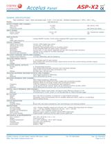
Accelus ASP-X2 Panel RoHS GENERAL SPECIFICATIONS Test conditions: Load = Wye connected load: 2 mH + 2 Ω line-line. Ambient temperature = 25°C, +HV = HVmax MODEL ASP-055-04-X2 OUTPUT POWER (PER CHANNEL) Peak Current Peak time Continuous current 4 (2.83) 1 Sec 3 (2.12) INPUT POWER HVmin~HVmax Input current PWM OUTPUTS Type PWM ripple frequency DIGITAL CONTROL Digital Control Loops Sampling rate (time) Commutation Modulation Bandwidths HV Compensation Minimum load inductance Adc (Arms), ±5% Adc (Arms) per phase +20 to +55 8.5 Vdc, Transformer-isolated Adc 3-phase MOSFET inverter, 15 kHz...
Open the catalog to page 2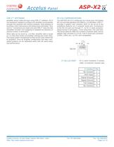
Accelus ASP-X2 Panel RoHS CME 2™ SOFTWARE RS-232 COMMUNICATIONS Amplifier setup is fast and easy using CME 2™ software. All of the operations needed to configure the amplifier are accessible through this powerful and intuitive program. Auto-phasing of brushless motor Hall sensors and phase wires eliminates “wire and try”. Connections are made once and CME 2™ does the rest thereafter. Encoder wire swapping to establish the direction of positive motion is eliminated. The ASP-055-04-X2 is configured via a three-wire, full-duplex RS-232 port that operates from 9600 to 115,200 Baud. CME 2™...
Open the catalog to page 3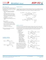
Accelus ASP-X2 Panel RoHS AMP STATUS LED ENABLE INPUTS Bi-color LEDs gives the state of each axis by changing color, and either blinking or remaining solid. The possible color and blink combinations are: The inputs are are common-anode opto-isolators that are 24 Vdc compatible. With the [ENABLE_COMM] connected to +24 Vdc, the [EN1] or [EN2] signals are then grounded by current-sinking outputs on the controller to enable the amplifier channels. • Green/Solid: Axis OK and enabled. Will run in response to reference inputs. +5V [EN_COMM] • Green/Slow-Blinking: Axis OK but NOT-enabled. Will run...
Open the catalog to page 4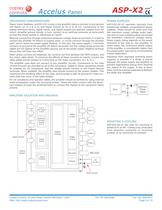
Accelus ASP-X2 Panel RoHS GROUNDING CONSIDERATIONS POWER SUPPLIES Power, motor feedback, and RS-232 circuits in the amplifier share a common circuit-ground (HV Return on J1-3 & J1-6, and Signal Ground on J4-13 & J5-13). Connections to the analog reference inputs, digital inputs, and digital outputs are optically isolated from HV return. Amplifier ground should, in turn, connect to an earthing conductor at some point so that the whole system is referenced to “earth”. ASP-055-04-X2 operates typically from transformer-isolated, unregulated DC power supplies. These should be sized such that the...
Open the catalog to page 5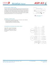
Accelus ASP-X2 Panel RoHS MOTOR PHASE CONNECTIONS The axis outputs are three-phase PWM inverters that convert the DC buss voltage (+HV) into three sinusoidal voltage waveforms that drive the motor phase-coils. Cable should be sized for the continuous current rating of the amplifier. Motor cabling should use twisted, shielded conductors for CE compliance, and to minimize PWM noise coupling into other circuits. The motor cable shields should connect to motor frame and the amplifier frame ground terminal (J2-1 or J3-1) for best results. = Shielded cables required for CE compliance FEEDBACK...
Open the catalog to page 6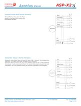
Accelus ASP-X2 Panel YASKAWA SIGMA MINI MOTOR FEEDBACK Black These CME 2 screens show the Basic Setup for the Sigma Mini motors with incremental encoders. J4, J5 6 A White/Black 7 Yellow 4 White/Yellow 5 Green 2 White/Green 3 ENCODER Red Black Green/Yel PANASONIC MINAS-A MOTOR FEEDBACK Red Panasonic motor Basic Setup is shown in these CME 2 screens. The encoders are 2500 line, or 10,000 counts after quadrature per revolution. Panasonic Minas-A motors use an 11-wire interface that has the A & B quadrature channels, an X index channel, and a fourth RX channel that contains encoder Hall state...
Open the catalog to page 7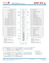
1. .590 TYP .1 .080 Accelus ASP-X2 Panel RoHS CONNECTORS PIN PIN J6 SIGNAL Frame Ground 1 14 [OUT1] 15 [OUTPUT_COMM] 16 [OUT2] 17 [OUT3] 18 [ENABLE_A] 19 [ENABLE_B] 20 [ENABLE_COMM] 21 Axis B Buff Enc Out X 22 Axis B Buff Enc Out /X 23 Axis B Buff Enc Out B 24 Axis B Buff Enc Out /B [OUT4] 2 Axis A Ref(+) 3 Axis A Ref(-) 4 Axis B Ref(+) 5 Axis B Ref(-) 6 Signal Ground 7 Axis A Buff Enc Out X 8 10 Axis A Buff Enc Out /B 1 14 J6 A/B 11 6.310 160.27 9 Axis A Buff Enc Out B 6.575 167.01 Axis A Buff Enc Out /X Ref Axis .133 3.38 J6 SIGNAL A 13 26 1 8 7 14 J5 Axis A Buff Enc Out A 12 25 Axis B...
Open the catalog to page 8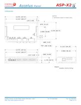
POWER MOTB MOT A FEEDBACK B FEEDBACK A SIGNAL 1. Dimensions shown in inches (mm).
Open the catalog to page 9All Copley Controls catalogs and technical brochures
-
XenusPLUS Compact EtherCAT XEC
30 Pages
-
XenusPLUS Compact CANopen XPC
30 Pages
-
Control Networks
8 Pages
-
R-Series Guide
8 Pages
-
Selection Guide
24 Pages
-
Xenus R10
30 Pages
-
Accelnet R23
24 Pages
-
Accelnet R22
22 Pages
-
Accelnet R21
24 Pages
-
Accelnet R20
24 Pages
-
Accelus Card Development Kit
6 Pages
-
Accelus Card
8 Pages
-
Junus
10 Pages
-
CAN-PCI-02
2 Pages
-
CAN-IPM-01
8 Pages
-
Bantam
18 Pages
-
Bantam R30
18 Pages
-
503
6 Pages
-
Power Supply Subsystem
8 Pages
-
Shunt Regulator
2 Pages
-
Xenus PLUS 2-Axis CANopen
34 Pages
-
Xenus RoHS PLUS CANopen
28 Pages
-
Xenus PLUS 2-Axis EtherCAT
34 Pages
-
Xenus PLUS EtherCAT
28 Pages
-
Xenus Edge Filter
16 Pages
-
Regen Resistors
24 Pages
-
Xenus Micro
24 Pages
-
Accelus Card Development Kit
6 Pages
-
Accelus Card
8 Pages
-
Accelus Panel
10 Pages
-
Xenus XTL
30 Pages
-
Accelnet Plus EtherCAT Panel
18 Pages
-
Accelnet Micro Module and Kit
24 Pages
-
Accelnet Micro Panel
24 Pages
-
Accelnet Module Development Kit
8 Pages
-
Accelnet Module
14 Pages
-
Accelnet Panel ADP
24 Pages


