
- Catalogs
- Copley Controls
- Accelus Card

- Products
- Catalogs
- News & Trends
- Exhibitions
Accelus Card

Accelus Card
The Accelus™ digital servoamplifier is engineered for driving DC brushless motors in modes such as position, velocity, or torque with full digital control. It employs sinusoidal commutation with encoder feedback and Hall signals for phase initialization and correction, ensuring efficient motor operation.
The servoamplifier supports field-oriented control to optimize speed and torque, minimizing motor heating and maximizing efficiency. It features auto-tuning and auto-phasing capabilities to reduce setup times. Compatible with motion controllers using incremental encoder feedback, it operates with both analog and digital control signals.
The amplifier can handle a peak current of up to 18 Amps DC and a continuous current of up to 6 Amps DC, depending on the model. It supports a wide input voltage range and uses a 3-phase MOSFET inverter for PWM outputs. The current loop update rate is 20 kHz, and it can process various reference inputs, including analog and digital signals.
Configuration is done via an RS-232 port, with CME 2™ software providing a graphical user interface for setup. It includes digital inputs for enabling the amplifier and controlling its state, as well as digital outputs for fault indication and motor brake control.
The amplifier includes protections against overvoltage, undervoltage, over-temperature, and short circuits. A bi-color LED indicates the amplifier's status, with different colors and blinking patterns representing various operational states and fault conditions.
Designed for PCB mounting, the amplifier can be installed at 0° or 90° angles. It is convection-cooled, with optional fan cooling for enhanced thermal management.
The Accelus™ servoamplifier offers advanced features for efficient motor control, with flexible configuration options and robust protection mechanisms, making it suitable for a wide range of industrial applications.
The document describes two formats for stepper-command signals: CW/CCW (clockwise/counter-clockwise) and Pulse & Direction. In CW/CCW, pulses at IN6 increase the position-command, while pulses at IN5 decrease it. In Pulse & Direction, pulses at IN6 adjust the position-command based on the DC level at the Direction input, IN5.
There are three types of motor connections: phase, Halls, and encoder. Phase connections carry amplifier output currents to drive the motor. Hall signals provide absolute position feedback within an electrical commutation cycle. Encoder signals offer incremental position feedback for velocity and position modes.
The motor encoder input circuit uses a differential line-receiver with R-C filtering. Differential outputs are preferred for noise reduction. Encoder cabling should use twisted pair cables for optimal noise rejection.
Hall signals are single-ended and provide absolute feedback within one electrical cycle. They are used for commutation-initialization and checking motor phasing after startup.
The amplifier connects to a three-phase PWM inverter, converting DC voltage into sinusoidal waveforms to drive motor phase-coils. Proper cabling and routing are essential to minimize noise.
Accelus operates from transformer-isolated, unregulated DC power supplies. External capacitance is required to handle ripple currents. Regulated switching power supplies can be used with a diode to prevent regenerative energy feedback.
All circuits share a common ground. High-current paths should connect to system-earth through the shortest path. Proper grounding minimizes voltage drops and noise.
Fusing protects external circuits and motors from amplifier failures. Motor phase fusing is recommended for linear motors due to their lower thermal capacity. Proper fuse sizing is crucial to prevent false-tripping.
The document details the connections for J1 and J2 connectors, emphasizing the importance of connecting all pins in a group for current-sharing.
The document provides instructions for ordering the Development Kit and related components, including part numbers and descriptions.
Catalog excerpts
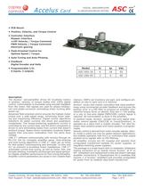
Accelus Card ASC DIGITAL SERVOAMPLIFIER for BRUSHLESS/BRUSH MOTORS RoHS • PCB Mount • Position, Velocity, and Torque Control • Controller Interface Stepper Interface ±10V Velocity / Torque Command PWM Velocity / Torque Command Electronic gearing • Field-Oriented Control for Optimal Speed / Torque • Auto-Tuning and Auto-Phasing • Feedback Digital Encoder and Halls description The Accelus™ servoamplifier drives DC brushless motors in position, velocity, or torque modes with 100% digital control. Commutation is sinusoidal using encoder feedback from the motor. Hall signals are used for phase-initialization and phase-correction eliminating motor hunting after power-up. Advanced field-oriented-control ensures the highest motor torque over a wide speed range, minimizing motor heating and maximizing efficiency. Digital control algorithms transform AC stator currents into direct and quadrature components. The torque-producing quadrature current is controlled by the current loop, and the direct component is driven to zero eliminating losses from current that doesn’t produce torque. Space-vector modulation produces higher speeds than sine-pwm modulation from the same buss voltage. CME 2™ software communicates with Accelus through an RS-232 link for complete amplifier setup. Auto-phasing and auto-tuning algorithms in CME 2™ slash set up times for fast system commissioning and eliminate “re-wire and try” so common in brushless motor installations. CME 2™ automates current loop tuning, as well as motor, Hall, and encoder phasing. A powerful oscilloscope and signal generator display amplifier performance for fine tuning thereafter. Amplifier control parameters are saved in non-volatile flash Model Ic Ip Vdc ASC-055-18 6 18 55 ASC-090-09 • Programmable I/O: 6 inputs, 2 outputs 3 9 90 memory. OEM’s can inventory one part, and configure amplifiers on-site to each axis in a machine. Accelus™ works with motion controllers that close positionloops using incremental encoder feedback and process the position error in a PID filter to produce an amplifier command for torque, force, or velocity. Only one +/-10V analog, or a one or two-wire digital PWM/(DIR) control signal is required. All commutation is done in the amplifier. In position-mode, Accelus™ accepts two-wire digital stepmotor control signals (CW/CCW, or Count/Direction), or operates as a slave from a master encoder. The ratio between input position pulses and motor position is programmable. Velocity control is derived from motor encoder signals. Velocity mode is useful not only for speed-setpoint applications, but enables operation with PLC’s or controllers that output position-error signals with no PID filtering. All amplifier circuits are DC coupled and operate from unregulated transformer-isolated DC power supplies, or regulated switching power supplies. The package is a single board with no heatplate. Solderless mating connectors on pc boards mount Accelus™ at 0° or 90°. Installation and replacement is fast and doesn’t damage amplifier connections. A Development Kit is available that mounts 1~4 Accelus™ amplifiers and provides unregulated DC power from an isolation step-down transformer. Copley Controls, 20 Dan Road, Canton, MA 02021, USA Tel: 781-828-8090 Tech Support: E-mail: [email protected], Web: http://www.copleycontrols.com Fax: 781-828-6547 Page 1 of 8
Open the catalog to page 1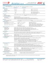
Accelus Card DIGITAL SERVOAMPLIFIER for BRUSHLESS/BRUSH MOTORS ASC RoHS GENERAL SPECIFICATIONS Test conditions: Load = 1mH in series with 1 Ohm. Ambient temperature = 25 deg. C. MODEL OUTPUT POWER Peak Current Peak time Continuous current INPUT POWER HVmin~HVmax PWM OUTPUTS Type PWM ripple frequency COMMUTATION & CONTROL Current loop update rate Commutation Phase Initialization ASC-055-18 ASC-090-09 18 (12.73) 1 6 (4.24) 9 (6.36) 1 3 (2.12) Amps DC (Amps ACrms) Sec Amps DC (Amps ACrms) 20~90 10 3.3 VDC, Transformer-isolated ADC (1 sec) peak input current ADC continuous current 20~55 20 6.7 3-phase...
Open the catalog to page 2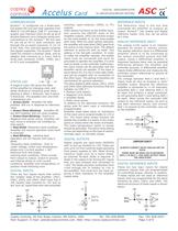
Accelus COMMUNICATION Accelus™ is configured via a three-wire, full-duplex RS-232 port that operates from 9600 to 115,200 Baud. CME 2™ provides a graphic user interface (GUI) to set up all of Accelus features via a computer serial port. Connections to the Accelus™ RS-232 port P1 are via an RJ-11 style connector, and through the pc board connector J1 (J1-19 & 20). RxD, TxD, and Gnd signals comprise the signals supported. The Accelus™ Serial Cable Kit contains a modular cable, and an adapter that connects to a 9-pin, Sub-D serial port connector (COM1, COM2, etc.) on PC’s and compatibles. STATUS...
Open the catalog to page 3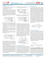
Accelus Card DIGITAL SERVOAMPLIFIER for BRUSHLESS/BRUSH MOTORS DIGITAL REFERENCE INPUTS (CONT’D) For torque or velocity control, the inputs may be configured in two formats: 1. PWM (0~100%) & Polarity 2. PWM (50%) In the first case, the PWM signal can vary from 0% to 100%, and the Polarity signal is a DC level that controls the direction of the motor. The PWM duty-cycle controls the amplifier output current, or motor velocity. In current mode, 100% corresponds to the maximum output current. In velocity mode, it commands the maximum velocity that is configured. Another type of PWM input is the...
Open the catalog to page 4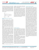
Accelus the phase conductors near to each other to maximize transmission-line effects, and to reduce noise coupling into adjacent circuitry. Motor cabling should use twisted, shielded conductors for best shielding and to minimize PWM noise coupling into other circuits. The motor cable shield should connect to motor frame and the amplifier high-current ground terminal (HV return) for best results. Card DIGITAL SERVOAMPLIFIER for BRUSHLESS/BRUSH MOTORS supplies in user equipment. These power supplies should also connect to the HV Return at a single point. The final configuration should embody three...
Open the catalog to page 5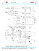
Accelus DIGITAL SERVOAMPLIFIER Card for BRUSHLESS/BRUSH MOTORS ASC RoHS AMPLIFIER CONNECTIONS 25 DAC Analog Torque or Velocity Reference Input ±10V Ref(+) Input 26 Encoder /A Neg Enable [IN4] 18 Signal Gnd 24 Signal Gnd Controller Digital I/O 15 TxD Controller RS-232 RxD I/O RxD TxD 9 2 Gnd 5 3 5 3 5 D-Sub 9-pos Female 6 Yellow 3 Hall W Fault Output [OUT2] 3 Red 2 Black V P1 6 +24V 5 1 3 5 2 4 6 Motor V 7 9 11 8 10 12 Motor U 13 15 17 14 16 Fuse 18 W Gnd 3 2 BRAKE 13 Motor W TxD HALLS W 4 /Brake Output [OUT1] Fuse V MOTOR RxD RJ-11 Modular Cable U Mount external capacitor <= 12" (30 cm) from...
Open the catalog to page 6All Copley Controls catalogs and technical brochures
 XenusPLUS Compact EtherCAT XEC
30 Pages
 XenusPLUS Compact CANopen XPC
30 Pages
 Control Networks
8 Pages
 R-Series Guide
8 Pages
 Selection Guide
24 Pages
 Xenus R10
30 Pages
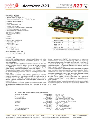 Accelnet R23
24 Pages
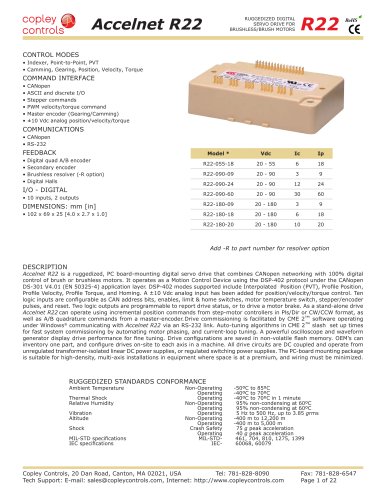 Accelnet R22
22 Pages
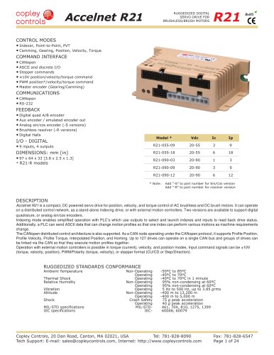 Accelnet R21
24 Pages
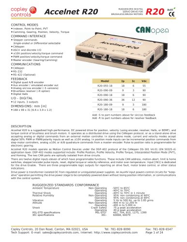 Accelnet R20
24 Pages
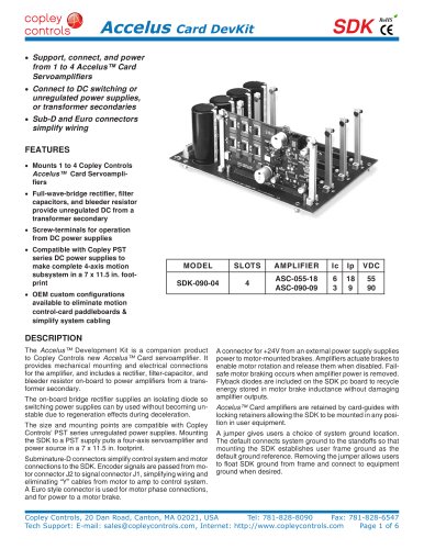 Accelus Card Development Kit
6 Pages
 ASP-X2 Accelus Panel Dual
10 Pages
 Junus
Junus10 Pages
 CAN-PCI-02
2 Pages
 CAN-IPM-01
8 Pages
 Bantam
18 Pages
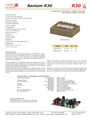 Bantam R30
18 Pages
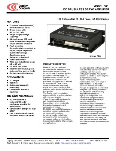 503
5036 Pages
 Power Supply Subsystem
8 Pages
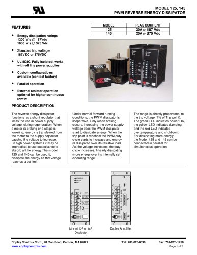 Shunt Regulator
2 Pages
 Xenus PLUS 2-Axis CANopen
34 Pages
 Xenus RoHS PLUS CANopen
28 Pages
 Xenus PLUS 2-Axis EtherCAT
34 Pages
 Xenus PLUS EtherCAT
28 Pages
 Xenus Edge Filter
16 Pages
 Regen Resistors
24 Pages
 Xenus Micro
24 Pages
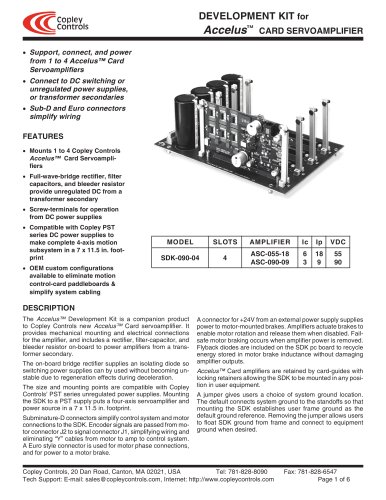 Accelus Card Development Kit
6 Pages
 Accelus Card
8 Pages
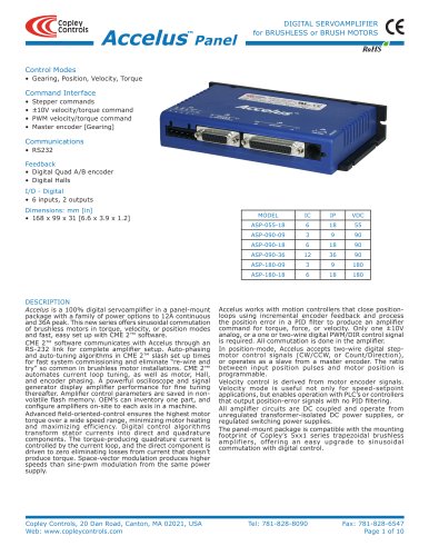 Accelus Panel
10 Pages
 Xenus XTL
30 Pages
 Accelnet Plus EtherCAT Panel
18 Pages
 Accelnet Micro Module and Kit
24 Pages
 Accelnet Micro Panel
24 Pages
 Accelnet Module Development Kit
8 Pages
 Accelnet Module
14 Pages
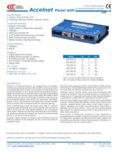 Accelnet Panel ADP
24 Pages





- Analog I/O
- Servo-amplifier
- Motor controller
- DC servo-amplifier
- Fieldbus servo-drive
- DC motor controller
- AC servo-amplifier
- Brushless servo-amplifier
- Stepper motor controller
- Communication interface card
- EtherCAT servo-amplifier
- Compact servo-amplifier
- CANopen servo-amplifier
- Digital servo-amplifier
- Stepper servo drive
- Industrial interface expansion card
- CANopen I/O
- Brushless motor control
- Digital input motor controller