
- Catalogs
- Copley Controls
- Accelnet R22

- Products
- Catalogs
- News & Trends
- Exhibitions
Accelnet R22
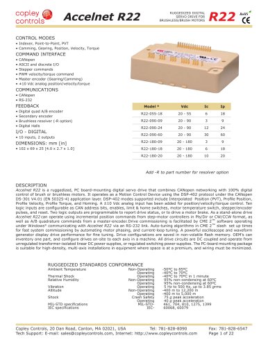
Accelnet R22
Catalog excerpts
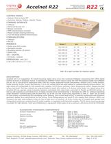
Accelnet R22 R22 RUGGEDIZED DIGITAL SERVO DRIVE FOR BRUSHLESS/BRUSH MOTORS RoHS CONTROL MODES • Indexer, Point-to-Point, PVT • Camming, Gearing, Position, Velocity, Torque COMMAND INTERFACE • • • • • • CANopen ASCII and discrete I/O Stepper commands PWM velocity/torque command Master encoder (Gearing/Camming) ±10 Vdc analog position/velocity/torque COMMUNICATIONS • CANopen • RS-232 FEEDBACK Model * Vdc Ic Ip R22-055-18 20 - 55 6 18 R22-090-09 20 - 90 3 9 R22-090-24 20 - 90 12 24 R22-090-60 20 - 90 30 60 DIMENSIONS: mm [in] R22-180-09 20 - 180 3 9 • 102 x 69 x 25 [4.0 x 2.7 x 1.0] R22-180-18 20 - 180 6 18 R22-180-20 20 - 180 10 20 • • • • Digital quad A/B encoder Secondary encoder Brushless resolver (-R option) Digital Halls I/O - DIGITAL • 10 inputs, 2 outputs Add -R to part number for resolver option DESCRIPTION Accelnet R22 is a ruggedized, PC board-mounting digital servo drive that combines CANopen networking with 100% digital control of brush or brushless motors. It operates as a Motion Control Device using the DSP-402 protocol under the CANopen DS-301 V4.01 (EN 50325-4) application layer. DSP-402 modes supported include Interpolated Position (PVT), Profile Position, Profile Velocity, Profile Torque, and Homing. A ±10 Vdc analog input has been added for position/velocity/torque control. Ten logic inputs are configurable as CAN address bits, enables, limit & home switches, motor temperature switch, stepper/encoder pulses, and reset. Two logic outputs are programmable to report drive status, or to drive a motor brake. As a stand-alone drive Accelnet R22 can operate using incremental position commands from step-motor controllers in Pls/Dir or CW/CCW format, as well as A/B quadrature commands from a master-encoder. Drive commissioning is facilitated by CME 2™ software operating under Windows® communicating with Accelnet R22 via an RS-232 link. Auto-tuning algorithms in CME 2™ slash set up times for fast system commissioning by automating motor phasing, and current-loop tuning. A powerful oscilloscope and waveform generator display drive performance for fine tuning. Drive configurations are saved in non-volatile flash memory. OEM’s can inventory one part, and configure drives on-site to each axis in a machine. All drive circuits are DC coupled and operate from unregulated transformer-isolated linear DC power supplies, or regulated switching power supplies. The PC-board mounting package is suitable for high-density, multi-axis installations in equipment where space is at a premium, and wiring must be minimized. RUGGEDIZED STANDARDS CONFORMANCE Ambient Temperature Thermal Shock Relative Humidity Vibration Altitude Shock MIL-STD specifications IEC specifications Non-Operating Operating Operating Non-Operating Operating Operating Non-Operating Operating Crash Safety Operating MIL-STDIEC- -50ºC to 85ºC -40ºC to 70ºC -40ºC to 70ºC in 1 minute 95% non-condensing at 60ºC 95% non-condensing at 60ºC 5 Hz to 500 Hz, up to 3.85 grms -400 m to 12,200 m -400 m to 5,000 m 75 g peak acceleration 40 g peak acceleration 461, 704, 810, 1275, 1399 60068, 60079 Copley Controls, 20 Dan Road, Canton, MA 02021, USA Tel: 781-828-8090 Tech Support: E-mail: [email protected], Internet: http://www.copleycontrols.com Fax: 781-828-6547 Page 1 of 22
Open the catalog to page 1
Accelnet R22 RUGGEDIZED DIGITAL SERVO DRIVE FOR BRUSHLESS/BRUSH MOTORS R22 RoHS GENERAL SPECIFICATIONS Test conditions: Load = Wye connected load: 1 mH+ 1Ω line-line. Ambient temperature = 25 °C. +HV = HVmax MODEL R22-055-18 OUTPUT POWER Peak Current 18 (12.7) Peak time 1 Continuous current 6 (4.24) Peak Output Power 0.99 Continuous Output Power 0.33 INPUT POWER HVmin to HVmax Ipeak Icont Aux HV R22-090-09 R22-090-24 R22-090-60 R22-180-09 R22-180-18 R22-180-20 9 (6.34) 1 3 (2.1) 0.81 0.27 24 (17.0) 1 12 (8.5) 2.16 1.08 60 (42.4) 1 30 (21.2) 5.4 2.7 9 (6.34) 1 3 (2.1) 1.62 0.54 18 (12.7) 1 6 (4.24)...
Open the catalog to page 2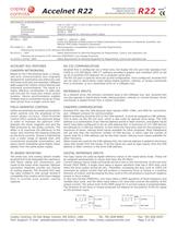
Accelnet R22 MECHANICAL & ENVIRONMENTAL Size Weight Contaminants Environment Cooling RUGGEDIZED DIGITAL SERVO DRIVE FOR BRUSHLESS/BRUSH MOTORS R22 RoHS 4.05 in (102.7 mm) X 2.62 in (66.5 mm) X 0.92 in (24.9 mm) 5.7 oz (0.16 kg) Pollution degree 2 IEC68-2: 1990 Heatsink required for continuous power output AGENCY STANDARDS CONFORMANCE EN 55011 : 2007 CISPR 11 : 2003/A2 : 2006 Limits and Methods of Measurement of Radio Disturbance Characteristics of Industrial, Scientific, and Medical (ISM) Radio Frequency Equipment EN 61000-6-1 : 2001 Electromagnetic Compatibility Generic Immunity Requirements...
Open the catalog to page 3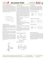
Accelnet R22 RUGGEDIZED DIGITAL SERVO DRIVE FOR BRUSHLESS/BRUSH MOTORS R22 RoHS ANALOG COMMAND INPUT DIGITAL INPUTS CAM MASTER An analog input is provided for position/velocity/ torque control. When using this input, Ref(+) and Ref(-) must both be connected to the controller. This differential connection is important for two reasons. First, for rejection of noise between controller and drive grounds. Second, because if one Ref input is left open, grounding of the other input will produce a ±2% of peak-current command, not a 0% command. There are ten digital inputs to Accelnet, nine of which can...
Open the catalog to page 4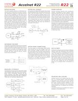
Accelnet R22 RUGGEDIZED DIGITAL SERVO DRIVE FOR BRUSHLESS/BRUSH MOTORS R22 RoHS MOTOR ENCODER MOTOR HALL SIGNALS POWER SUPPLIES The motor encoder interface is a differential linereceiver with R-C filtering on the inputs. Encoders with differential outputs are preferred because they are less susceptible to noise that can be picked on single-ended outputs. PC board layouts should route the encoder signal-pairs as close to each other as possible for best transmission-line characteristics. If single-ended encoders are used, a pull-up resistor should be installed on the PC board, and the unused input...
Open the catalog to page 5
Accelnet R22 RUGGEDIZED DIGITAL SERVO DRIVE FOR BRUSHLESS/BRUSH MOTORS Quad A/B TYPICAL DRIVE CONNECTIONS Enable 19 Enable Input [IN1] GPIn 18 Fwd Enable [IN2] GPIn PosLim Encoder A 32 Motion Controller Rev Enable 20 [IN3] GPIn Encoder B Encoder /B 27 Encoder /X 28 Hall U 25 Hall V 23 Hall W 26 22 Signal Gnd 10 DAC ±10V B 30 Encoder X /A 29 21 Signal Gnd NegLim A 31 Encoder /A Fault Output [OUT1] 8 ±10V Ref(+) 7 ±10V Ref(-) R22 RoHS ENCODER /B X /X U V HALLS W J2 17 [IN4] GPIn 15 [IN6] HSIn A Secondary Encoder Optional B Camming Master Encoder (Optional) A B Controller RS-232 I/O CANH CANL Gnd...
Open the catalog to page 6All Copley Controls catalogs and technical brochures
 XenusPLUS Compact EtherCAT XEC
30 Pages
 XenusPLUS Compact CANopen XPC
30 Pages
 Control Networks
8 Pages
 R-Series Guide
8 Pages
 Selection Guide
24 Pages
 Xenus R10
30 Pages
 Accelnet R23
24 Pages
 Accelnet R21
24 Pages
 Accelnet R20
24 Pages
 Accelus Card Development Kit
6 Pages
 Accelus Card
8 Pages
 ASP-X2 Accelus Panel Dual
10 Pages
 Junus
Junus10 Pages
 CAN-PCI-02
2 Pages
 CAN-IPM-01
8 Pages
 Bantam
18 Pages
 Bantam R30
18 Pages
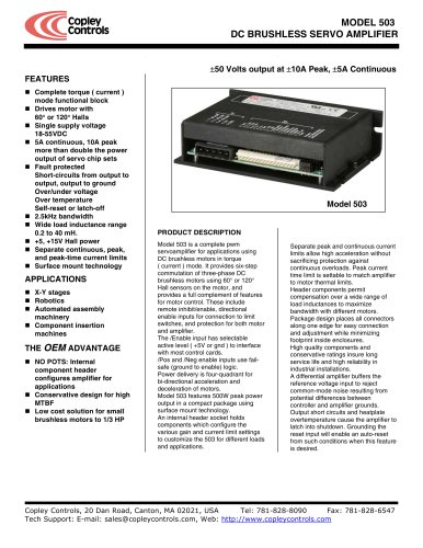 503
5036 Pages
 Power Supply Subsystem
8 Pages
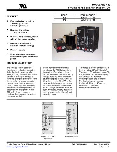 Shunt Regulator
2 Pages
 Xenus PLUS 2-Axis CANopen
34 Pages
 Xenus RoHS PLUS CANopen
28 Pages
 Xenus PLUS 2-Axis EtherCAT
34 Pages
 Xenus PLUS EtherCAT
28 Pages
 Xenus Edge Filter
16 Pages
 Regen Resistors
24 Pages
 Xenus Micro
24 Pages
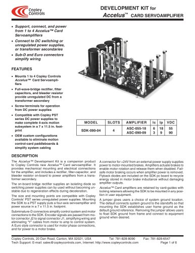 Accelus Card Development Kit
6 Pages
 Accelus Card
8 Pages
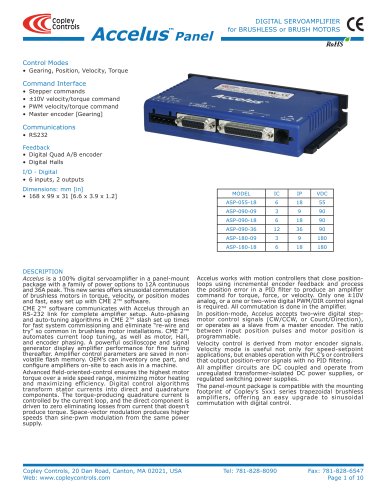 Accelus Panel
10 Pages
 Xenus XTL
30 Pages
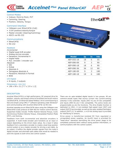 Accelnet Plus EtherCAT Panel
18 Pages
 Accelnet Micro Module and Kit
24 Pages
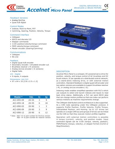 Accelnet Micro Panel
24 Pages
 Accelnet Module Development Kit
8 Pages
 Accelnet Module
14 Pages
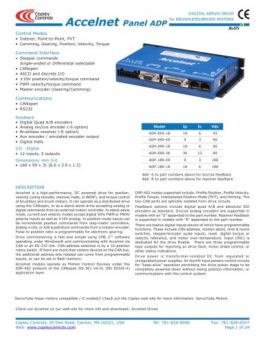 Accelnet Panel ADP
24 Pages





- Digital I/O
- Analog I/O
- Servo-amplifier
- DC servo-amplifier
- Fieldbus servo-drive
- DC motor controller
- AC servo-amplifier
- Brushless servo-amplifier
- Stepper motor controller
- Communication interface card
- EtherCAT servo-amplifier
- Compact servo-amplifier
- CANopen servo-amplifier
- Digital servo-amplifier
- Stepper servo drive
- Industrial interface expansion card
- CANopen I/O
- Brushless motor control
- Digital input motor controller