
- Catalogs
- Copley Controls
- Accelnet Plus EtherCAT Panel

- Products
- Catalogs
- News & Trends
- Exhibitions
Accelnet Plus EtherCAT Panel
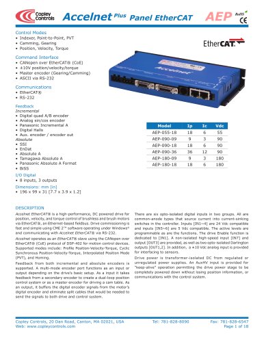
Accelnet Plus EtherCAT Panel
Catalog excerpts
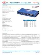
Model Ip Ic Vdc AEP-055-18 18 6 55 AEP-090-09 9 3 90 AEP-090-18 18 6 90 AEP-090-36 36 12 90 AEP-180-09 9 3 180 AEP-180-18 18 6 180 Copley Controls, 20 Dan Road, Canton, MA 02021, USA Tel: 781-828-8090 Fax: 781-828-6547 Web: www.copleycontrols.com Page 1 of 18 AEP Accelnet Plus Panel EtherCAT There are six opto-isolated digital inputs in two groups. All are common-anode types that source current into current-sinking switches in the controller. Inputs [IN1~4] are 24 Vdc compatible and inputs [IN5~6] are 5 Vdc compatible. The active levels are programmable as are the functions. The drive Enable function is dedicated to [IN1]. A non-isolated high-speed input [IN7] and output [OUT3] are provided, as well as two opto-isolated Darlington outputs [OUT1,2]. In addition, a ±10 Vdc analog input is provided for interfacing to sensors. Drive power is transformer-isolated DC from regulated or unregulated power supplies. An AuxHV input is provided for “keep-alive” operation permitting the drive power stage to be completely powered down without losing position information, or communications with the control system. descriptiondescription Accelnet EtherCAT® is a high-performance, DC powered drive for position, velocity, and torque control of brushless and brush motors via EtherCAT®, an Ethernet-based fieldbus. Drive commissioning is fast and simple using CME 2™ software operating under Windows® and communicating with Accelnet EtherCAT® via RS-232. Accelnet operates as an EtherCAT® slave using the CANopen over EtherCAT® (CoE) protocol of DSP-402 for motion control devices. Supported modes include: Profile Position-Velocity-Torque, Cyclic Synchronous Position-Velocity-Torque, Interpolated Position Mode (PVT), and Homing. Feedback from both incremental and absolute encoders is supported. A multi-mode encoder port functions as an input or output depending on the drive’s basic setup. As a input it takes feedback from a secondary encoder to create a dual-loop position control system or as a master encoder for driving a cam table. As an output, it buffers the digital encoder signals from the motor’s digital encoder and eliminate split cables that would be needed to send the signals to both drive and control system. Control Modes • Indexer, Point-to-Point, PVT • Camming, Gearing • Position, Velocity, Torque Command Interface • CANopen over EtherCAT® (CoE) • ±10V position/velocity/torque • Master encoder (Gearing/Camming) • ASCII via RS-232 Communications • EtherCAT® • RS-232 Feedback Incremental • Digital quad A/B encoder • Analog sin/cos encoder • Panasonic Incremental A • Digital Halls • Aux. encoder / encoder out Absolute • SSI • EnDat • Absolute A • Tamagawa Absolute A • Panasonic Absolute A Format • BiSS I/O Digital • 8 inputs, 3 outputs Dimensions: mm [in] • 196 x 99 x 31 [7.7 x 3.9 x 1.2]RoHSCopleyControls
Open the catalog to page 1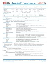
Copley Controls, 20 Dan Road, Canton, MA 02021, USA Tel: 781-828-8090 Fax: 781-828-6547 Web: www.copleycontrols.com Page 2 of 18 AEP Accelnet Plus Panel EtherCAT GENERAL SPECIFICATIONS Test conditions: Load = Wye connected load: 2 mH + 2 Ù line-line. Ambient temperature = 25°C, +HV = HVmax MODEL AEP-055-18 AEP-090-09 AEP-090-18 AEP-090-36 AEP-180-09 AEP-180-18 Output Power Peak Current 18 (12.7) 9 (6.4) 18 (12.7) 36 (25.5) 9 (6.4) 18 (12.7) Adc (Arms-sine), ±5% Peak time 1 1 1 1 1 1 Sec Continuous current 6 (4.2) 3 (2.1) 6 (4.2) 12 (8.5) 3 (2.1) 6 (4.2) Adc (Arms-sine) per phase Output resistance...
Open the catalog to page 2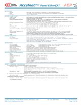
Copley Controls, 20 Dan Road, Canton, MA 02021, USA Tel: 781-828-8090 Fax: 781-828-6547 Web: www.copleycontrols.com Page 3 of 18 Accelnet Plus Panel EtherCAT AEP RS-232 PORT Signals RxD, TxD, Gnd in 6-position, 4-contact RJ-11 style modular connector. Mode Full-duplex, DTE serial port for drive setup and control, 9,600 to 115,200 Baud Protocol ASCII or Binary format motormotormotor connections Phase U, V, W PWM outputs to 3-phase ungrounded Wye or delta connected brushless motors, or DC brush motors Hall U, V, W Digital Hall signals, single-ended Digital Incremental Encoder Quadrature signals,...
Open the catalog to page 3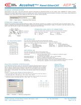
S1 S2 Hexex Dec 0 0 0 1 16 1 2 32 2 3 48 3 4 64 4 5 80 5 6 96 6 7 112 7 8 128 8 9 144 9 A 160 10 B 176 11 C 192 12 D 208 13 E 224 14 F 240 15 Copley Controls, 20 Dan Road, Canton, MA 02021, USA Tel: 781-828-8090 Fax: 781-828-6547 Web: www.copleycontrols.com Page 4 of 18 Accelnet Plus Panel EtherCAT AEP S1 S2 EtherCAT® Addressddressddressddress (stationstationstation aliasalias) In an EtherCAT® network, slaves are automatically assigned addresses based on their position in the bus. But when the device must have a positive identification that is independent of cabling, a Station Alias is needed....
Open the catalog to page 4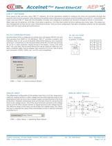
Copley Controls, 20 Dan Road, Canton, MA 02021, USA Tel: 781-828-8090 Fax: 781-828-6547 Web: www.copleycontrols.com Page 5 of 18 Accelnet Plus Panel EtherCAT AEP analoganalog INP U T The differential configuration of the analog input has a ±10 Vdc range and is useful for reading sensors or other voltage sources while rejecting noise on the signal ground that can occur due to power supply currents flowing in the wires to the drive. Shielded, twisted-pair wires are the best choice for connecting the input to the voltage source. One of the input terminals connects to the voltage source and the other...
Open the catalog to page 5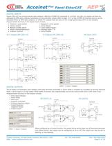
Copley Controls, 20 Dan Road, Canton, MA 02021, USA Tel: 781-828-8090 Fax: 781-828-6547 Web: www.copleycontrols.com Page 6 of 18 Accelnet Plus Panel EtherCAT AEP DIGITAL OUTPUTS Two of these are Darlington opto-isolators with both terminals accessible. A Zener diode is included as a snubber for driving inductive loads. A third output is a high-speed CMOS buffer. Functions are programmable, as are the active levels (ON or OFF when True). Programmable functions of the outputs include: • Drive fault indicator • Motor brake • PWM sync • Program controlled • Custom trajectory status • Custom position-...
Open the catalog to page 6All Copley Controls catalogs and technical brochures
 XenusPLUS Compact EtherCAT XEC
30 Pages
 XenusPLUS Compact CANopen XPC
30 Pages
 Control Networks
8 Pages
 R-Series Guide
8 Pages
 Selection Guide
24 Pages
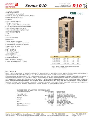 Xenus R10
30 Pages
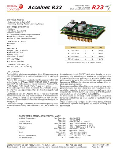 Accelnet R23
24 Pages
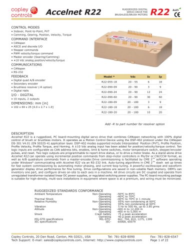 Accelnet R22
22 Pages
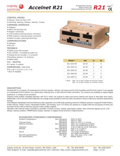 Accelnet R21
24 Pages
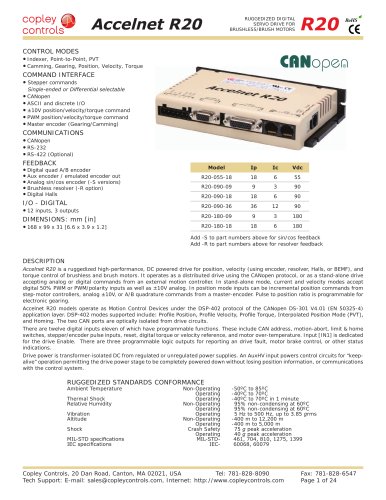 Accelnet R20
24 Pages
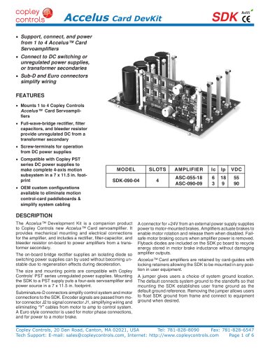 Accelus Card Development Kit
6 Pages
 Accelus Card
8 Pages
 ASP-X2 Accelus Panel Dual
10 Pages
 Junus
Junus10 Pages
 CAN-PCI-02
2 Pages
 CAN-IPM-01
8 Pages
 Bantam
18 Pages
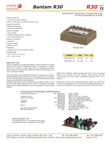 Bantam R30
18 Pages
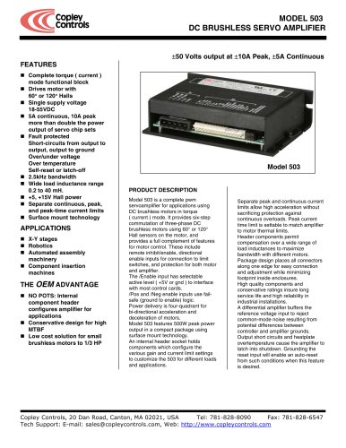 503
5036 Pages
 Power Supply Subsystem
8 Pages
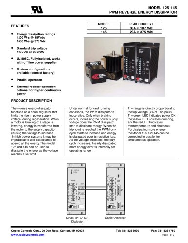 Shunt Regulator
2 Pages
 Xenus PLUS 2-Axis CANopen
34 Pages
 Xenus RoHS PLUS CANopen
28 Pages
 Xenus PLUS 2-Axis EtherCAT
34 Pages
 Xenus PLUS EtherCAT
28 Pages
 Xenus Edge Filter
16 Pages
 Regen Resistors
24 Pages
 Xenus Micro
24 Pages
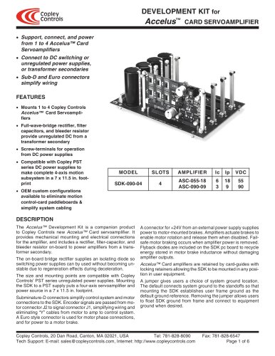 Accelus Card Development Kit
6 Pages
 Accelus Card
8 Pages
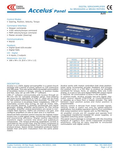 Accelus Panel
10 Pages
 Xenus XTL
30 Pages
 Accelnet Micro Module and Kit
24 Pages
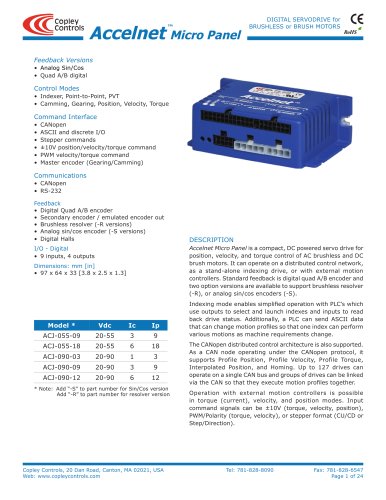 Accelnet Micro Panel
24 Pages
 Accelnet Module Development Kit
8 Pages
 Accelnet Module
14 Pages
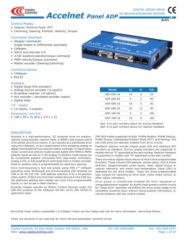 Accelnet Panel ADP
24 Pages





- Digital I/O
- Analog I/O
- Servo-amplifier
- Motor controller
- DC servo-amplifier
- Fieldbus servo-drive
- DC motor controller
- AC servo-amplifier
- Brushless servo-amplifier
- Stepper motor controller
- Communication interface card
- EtherCAT servo-amplifier
- Compact servo-amplifier
- CANopen servo-amplifier
- Digital servo-amplifier
- Stepper servo drive
- Industrial interface expansion card
- CANopen I/O
- Brushless motor control
- Digital input motor controller